


alsfarms
-
Posts
6,170 -
Joined
-
Last visited
Content Type
Forums
Gallery
Events
Everything posted by alsfarms
-
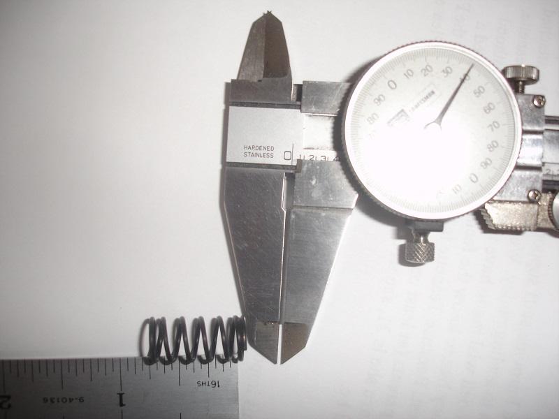
Here are the specifications for the spring that came in the check valve. I will attach a couple of images. Number of coils: 6 Height: 3/4" Wire OD: .040 Coil OD: 3/8" Al
-
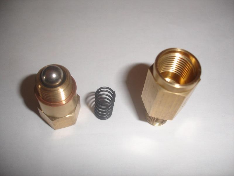
I did some exploratory surgery on one of these brass check valves. The attached image shows what I found. These are very simple check valves and are well suited for my intended low operating pressure use. I just need both of these valves to cycle at a lower, than the 90 PSI that the current spring allows. More later on my resolution. Al
-
The pressurized fuel delivery system, used on the Locomobile, requires the use of two 1/4" brass check valves. The first one is used to allow the manual pump to pull outside air into the pump barrel, that check valve #1 is to open when the pump handle is pulled loading the pump barrel. The second check valve #2 is used to close and stop the pressure flow from the fuel tank while the manual pump is pulling in fresh air. Then when the pump handle is pushed down the #1 check valve closes and stops the air flow back to atmosphere and the second check valve #2 is pushed open to allow the pressure to be pumped into the tank. This will work nicely, but, I need to open up the check valves and replace the stiff springs with ones that will cycle in at a much lower working PSI. More on that later. Here is an image of the check valves, nice and tidy. Al

-
I will let you know what I can find...... Al
-
David, I have heard that someone is reproducing this fuel gauge. I will try to track down who is doing that reproduction and post here if I can. I have an original Locomobile fuel gauge unit, but plan to use it on my project. How deep is your tank? Al
-
Note: The above shown threaded fitting is a straight thread, not a pipe thread. The seal is with a gasket located in the bottom of the female threads and will make up with a flat gasket face on the end of the male fitting. Al
-
I will now show the latest headache I have with the fuel delivery system. The shown image is of the bottom threads on the brass hand pressure pump. I had determined that the threads must have been BSPP. I purchased a reducing bushing to allow me to adapt the manual air pump to the fuel pressure system. I have learned that the fitting is not BSPP after all. I am going to try an SAE fine threaded fitting tomorrow. If that is not correct, I will be custom machining a brass reducing bushing for that location and application. Al

-
Before I get to my next part of the fuel delivery dilemma, I will shift gears and show a nice original piece of literature that I have just purchased. The image shows an original 1909 Locomobile Model 30 and 40 Service and Operator manual. It does not take much of a search to locate copies of , what is referred to as a "Locomobile Book". These books are basically sale related publicity books and were printed for a run during the early years of Locomobile. I have a couple of these "Books" and while they do show some pictures and give some information they are not intended to be a service or operators manual. I am very impressed with this new acquisition. I may show a few pages here as time moves along. I have also decided that as rare as the actual early Locomobile automobile may be, proper era literature is even more rare! Al

-
Here is a picture of the first step in the modification of the "T" fitting for the back of the air pressure gauge. The female threads have been drilled out to 9/16". I am not sure that I will have enough wall thickness to build the threaded sleeve. I am going to give one more try with a 4 flute end mill and go larger to 5/8". That will make the wall thickness of the "T" fitting thin but will leave me a bit more elbow room for machining the threaded sleeve. This is an ongoing project until I get a suitable fix that will allow me to properly thread the "T fitting onto the back of the air gauge. Some simple little issues can sure grow legs and run around making trouble! Al

-

REPORTS ON A 1914 HUMBERETTE RESTORATION
alsfarms replied to Mike Macartney's topic in Our Cars & Restoration Projects
Hello Joe and Mike, Pistons are the very heart of any engine for sure. It may be worth a call to the US company "Arias Pistons" located on the west coast of the US. I have already been in touch with them to see if they have a forged blank that has the dimensions compatible to finish machine to the size required for my Wisconsin project (same bore and stroke as Terry's Wisconsin only mine is a four cylinder road engine not a six cylinder). Arias has a huge number of pattern blanks for many different applications. Yes they do have a blank that will work for my application. When I am ready, for pistons, I will be going back to Arias for the finished piston set. Sadly, we are still dealing with snow and cold here in the western US so I am not so excited to get out and freeze my rear. Al -
Hello Mike, Did you and Joe get all the engineering issues resolved? 🙂 The internet is, in fact, a good medium to let all us crazies to network with each other quickly. I forced myself to join the modern world and use this internet to a much better extent. I do remember how slow it was to post a "snail mail" letter ask questions, make comments. Then wait for a couple of weeks only to do the same process again and again. SLOW is the word! I used to keep a log book of who I had letters out to and who I expected letters from so I didn't double up after a few months. Sometime, in the future, I would like to come to England and search out my, and my wife's, ancestral homeland. (I also have friends and relatives to visit). What is your latest development on your project. While my Locomobile is getting the fuel delivery system designed and sorted out, I am also looking into getting new main leaves build for all four of my springs. These are actually new built springs, but the builder, 10 years ago, didn't do a good job forming the eyes. They are just not going to work! The rest of the spring stack will be beautiful, tapered and rounded just as they should be. I will follow up with pictures. Have a good day.... and thanks for your response... Al
-
This picture shows the female thread that I will be drilling out, then inserting a 1/2" female Fine SAE threaded insert bushing, (homemade) and then soldering it into place. I will then have the correct "Tee" fitting, with all the correct threads. I did not want a big "dog knot" of fittings to adapt to what I needed, which was the other option, (unacceptable). If anyone has a brighter idea, speak up. Al

-
This picture will show the "Tee" fitting, set in place, as I need it to properly fit.

-
While going about the business of putting together an order list of fittings and small things needed to plumb in the fuel delivery system, I have encountered an issue with obsolete fittings. The attached images will let you see what I am dealing with. The back side of the Locomobile script air gauge has a 1/2" fine SAE male thread. I need to connect with a "Tee" fitting with flare fittings to allow fitment into the tubing system. The problem is I can't locate a "Tee" fitting with the correct female 1/2" Fine SAE thread. This image shows the back of the gauge with the "Tee" fitting, male thread exposed.

-
Here is another piece that will be placed in the fuel pressure system. These attached images show two sides of a 1/8" pipe thread shut-off valve. This may be a modern piece but it has the flavor of a style that would be appropriate for a 1909 car. This shut-off valve will be in line to isolate the engine from the pressure system, when using the hand pump to build the needed 2 PSI in the tank to start the car initially. Once running, the handle side of the valve, seen from the drivers eat and located on the dash board, can then be opened allowing engine compression pressure into the pressure system to maintain the 2 PSI requirement in the fuel delivery system. The handle side will be visible and operated from the drivers seat. The back side of the valve is what will be visible on the engine side fire wall. One note, I will design and have a custom brass handle cast to replace the die cast handle shown in the image. The brass handle will be larger and be styled after a more correct vintage handle I have. This shut-off valve is just one more piece of the pressure fuel system puzzle. Al


-
My 1910 Mitchell "parts car" project
alsfarms replied to JV Puleo's topic in Our Cars & Restoration Projects
Hello Joe, Well have a good time and say hello to Mike for the rest of us here in the USA. Al -
1922-23 Dodge Bros. Sidescreen question
alsfarms replied to alsfarms's topic in Dodge & Dodge Brothers
Hello And thanks for the pictures and measurements. I will compare your door opening with my touring car and see if they are the same. My cut down sidescreen project came with a running engine and front half of the frame with the factory fuel tank still in place under the seat. That was my first hint that I actually have a screenside not a passenger car. I also have the cowl which was cut in the middle of the door opening. I have enough spare frame pieces and a rear end to build the chassis back to stock. I think I may have a spare windshield assembly and doors. I am weak on front fenders, cab quarter panels and back panel. I do have the hinged back rest brackets and the back panel of the cab. My touring doors appear to be the same as what would fit your screenside door opening at 20". I was hoping that a touring center section would be wide enough to modify as is. That is not the case. I would need to locate two center sections to get enough body skin material in order to build the proper quarter panels. I can see now that knowing the out to out measurement, of the body at the back corners would help me have the overall rear body width. Jan could you measure across the back of your body? Looking for 1923 front fenders, quarter panels and cab back panel, (or I will be building them). Al -
Here is another piece of the puzzle as I put together a substantial fuel delivery system. This attached piece is an all brass gasoline sediment receiver. Like the other items shown here, I will be cleaning and verify proper working order before I install. This particular brass sediment bowl has been Nickel plated. That will be removed and the brass polished. Has anyone seen another sediment bowl of this design? The number B 2050 is cast into this piece on the horizontal inlet. Al

-
Early style cast brass gas tank fittings needed
alsfarms replied to alsfarms's topic in HCCA General Discussion
Thanks for the McMaster Carr reference. They have a huge inventory of various parts for sure. None of what I see will work for my application. Al -
Early style cast brass gas tank fittings needed
alsfarms replied to alsfarms's topic in HCCA General Discussion
Still on the hunt for gas tank or fittings thereof...... -
The next piece of the pressurized fuel system for the Locomobile is a Gray-Hawley pressure regulating valve. The attached pictures show this unit and shows how to plumb it into the fuel system. It allows for a source of compressed air to be pulled from an engine cylinder then reduced to the working pressure of 2 PSI that will be routed to the fuel tank. This unit also has provision for a cooling circuit that pulls cooling water from the radiator system. The third option on this unit is to allow for a charge of priming fuel to be made available to the cylinder for starting. By cooling down the compressed cylinder air it is safe to send the 2 PSI air to the tank to force fuel to the carburetor. This is a very interesting piece of early engineering to accomplish getting fuel to the carburetor with really no moving parts other that the reciprocating motion of a cylinder. Al
.thumb.jpg.97944e83e31810acae455b106700e54f.jpg)

-
REPORTS ON A 1914 HUMBERETTE RESTORATION
alsfarms replied to Mike Macartney's topic in Our Cars & Restoration Projects
Hello Mike, The wheels sure look nice and I bet it is a nice feeling to be to the point of rolling your frame around! Have you had any of you past wheel projects powder coated? I had a set of 30 x 3.5 Houk Model T wire wheels powder coated. They turned out very nice but were still a handful to mount the tires. The thing I like, about powder coating wheels, is the fact that they are a bit more tolerant to "fighting" the tires on with out damaging the paint! Will you be doing your own tube forming for the exhaust system? I see nothing wrong, at all, with your wife nudging you towards blue. It would be boring if we had all our cars painted the same color. One of my favorite colors is a nice deep rich blue, oh yeah. Keep up the good work/ Al -
Next in order to start a car, that does not have a working gravity system do deliver the fuel to the carburetor, is the hand pump. The hand pump should only be used to build the initial pressure, at the gasoline tank, and used to get the car started. After that point the rest of the fueling system should take over and provide the needed 2 PSI to keep the fuel under pressure and moving toward the carburetor. This is the hand pump, all brass. I am currently trying to decide where to locate and mount the pump for the best appearance and convenience. Any ideas from those of you that are using a hand pump? Al

-
Hudson Super Six 1929 Racer
alsfarms replied to VintageRacingCar's topic in Automobiles and Parts - Buy/Sell
I am curious, as I have never been around a Hudson Super 6. What is the CID of the engine, what type of mechanical redo was completed? Are the wheels Hudson or are they Buffalo refitted originally? Is the body the virgin piece? How about a better shot of the cockpit. I do certainly admire and enjoy this type of car but I was not quick enough to become a Doctor or Lawyer or inherit a thriving business where I could afford this quality of car. Good luck with the sale. Al -
Next in line with the manual hand pump to build pressure is the dash pressure gauge, This gauge allows the driver to verify that the fuel pressure system has enough pressure (but not to much) in order to push fuel up to the carburetor. The pressure is generally set at 2 PSI. Al


.jpg.1b2c48a03b716d04a20a8e56535b736f.jpg)


