

Gary W
-
Posts
1,062 -
Joined
-
Last visited
-
Days Won
14
Content Type
Forums
Gallery
Events
Everything posted by Gary W
-

1937 Buick Model 48: RESTORATION HAS BEGUN! (Photo)
Gary W replied to Gary W's topic in Buick - Pre War
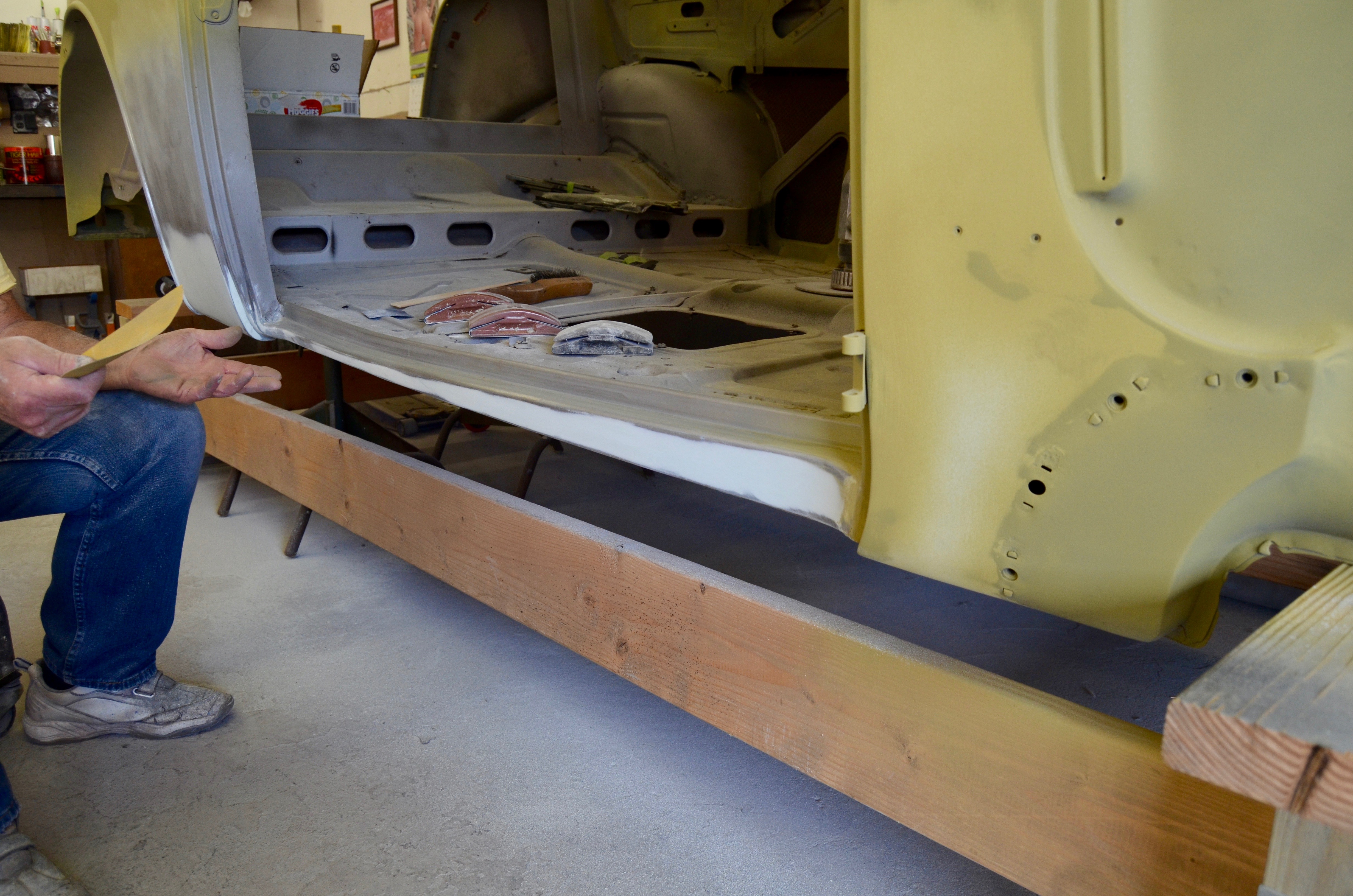
Saturday July 22, 2017: Update progress on the body work: I stopped by the painter's shop this morning to check on the body progress. There is another car in the shop that is taking Bob's time right now, but here is the progress as of today: In the last episode, our patch panel was just getting spot welded in to position. The weld was carried across the entire seam of the patch panel. Fiberglass body filler mixed and applied to a couple of areas. Namely under the door sill where there were a bunch of small pin holes and to the seam of the patch panel. The fiber glass is stringy when applied. I don't know the cure time until you can sand it. Days later, Bob is sanding the fiberglass smooth under the door sill. Glass applied to the seam as well, and smoothed out. Next comes the body filler triumvirate. The small tube in front is some sort of hardener/catalyst/accelerator.... Pumping the metal glaze into the Evercoat base. Then adding a drop of the accelerator. Literally... a drop! Being it was over 96 degrees today, this stuff set fast! Begin mixing, being careful not to incorporate too much air. Begin application Continuing down the door sill The application process is complete, and this stuff is already curing! Being it was cured and hard enough to sand in about 10 minutes, Bob sanded off the high spots, then progressively sanded it down to a 320. The door sill looks very nice at this point and... .....is very, very smooth to the touch! Demonstrating the straightness of the blend. Then on to sand the inner wheel wells in preparation for the yellow self-etching prime coat. He hopes to have the whole car in yellow Monday, then two coats of build-up grey primer. Interesting photos: While making the repair on the other car that was in the shop this week, Bob had a little build-up prime left in the gun, so he shot a couple of areas of the body. Here you see the primer on the firewall, and when I came in the shop, he wanted to show me what the build-up primer can do. This area looked really nice to me. I was happy to see the metal so smooth. But then Bob showed me something I thought was really cool: He sanded the area with a 320, lightly going over the primed area. It revealed that there are actually slight undulations to the paint that are not detectable to the eye! Here you can see what the build-up primer does! By filling in all the low spots, your final product comes out so much better. It now gets a second coat of the build-up primer applied, then a final sanding before color. (I thought that was pretty neat) And now a question: Can someone tell me what these "bump-outs" are for that are pressed into the body? Bob and I thought they were to make room for the window drain, but the drain runs much more forward. Driver's side. Just ahead of the rear seat. Passenger's side. (You can see the inside of the patch panel in this photograph) Have a great day! Gary


-
Congratulations and you've come to the right place! These guys are first rate and very knowledgeable! I bought my first Buick November (2016) and this forum has been the best help throughout the restoration! Many safe miles to you!
-
1937 Buick Model 48: RESTORATION HAS BEGUN! (Photo)
Gary W replied to Gary W's topic in Buick - Pre War
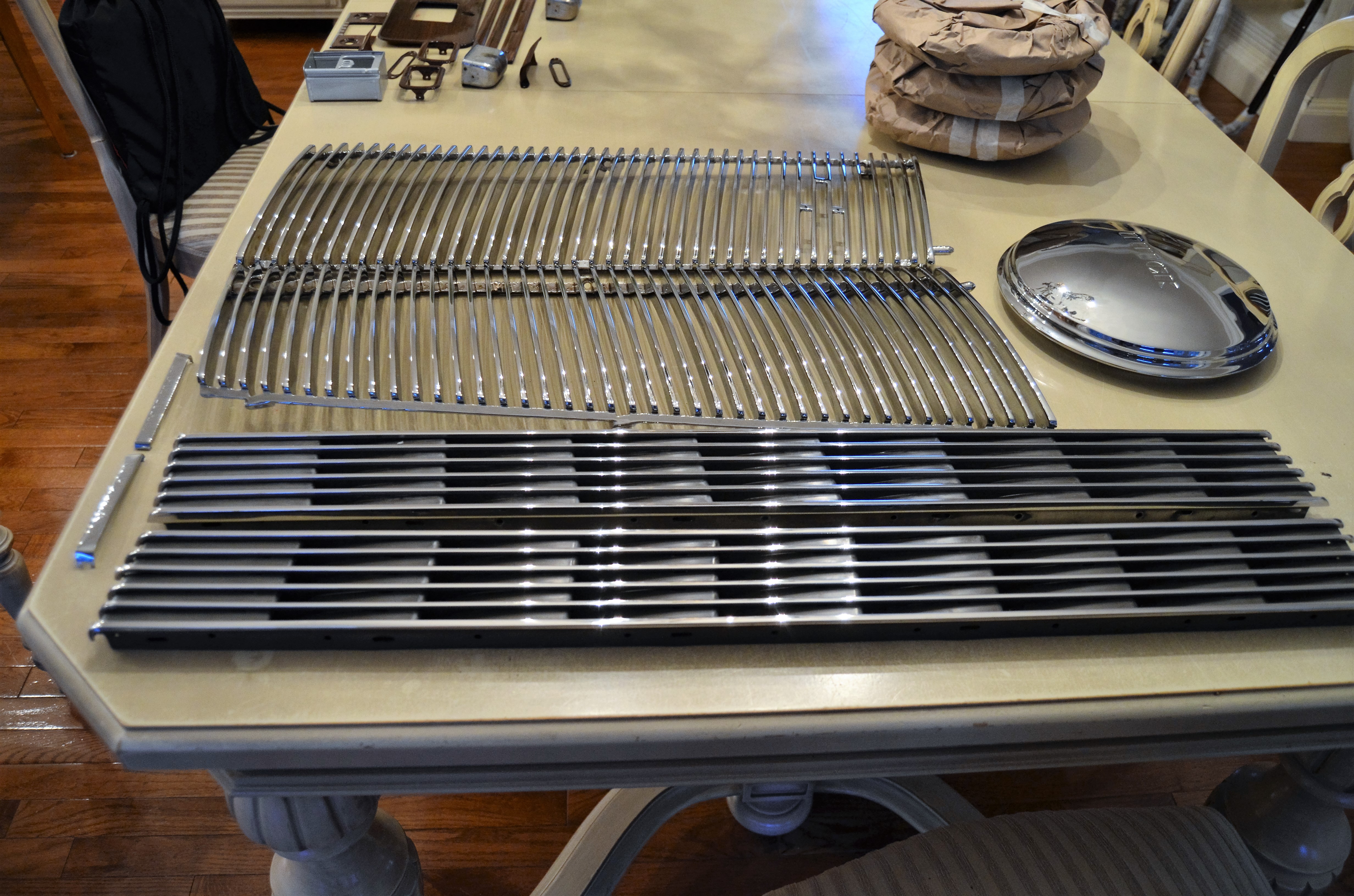
Wednesday July 19, 2017: Woodgrain and the rest of the Chrome is finished! Hello out there! It's been over a week since I've posted, but I assure you the work continues, maybe not at such a frenzied pace (this summer heat slows me down!), but still plodding along! John and I are finishing up painting the heater, emergency brake handle and steering column. The painter is still moving on the body (he had a couple other jobs squeezed into his schedule, so work on the Buick has stalled until the shop clears out). I'm still doing other things like cleaning and painting fasteners, and today I'd like to mark (label) the original headliner bows so I can clean them up and re-install them into the new headliner in the same position they came from. Yesterday FedEx dropped off four huge boxes with the rest of my chrome order from Paul's Chrome Plating and all my woodgrained parts came in. They were all done by Mr. Bob Kennedy in Whittier California. Beautiful craftsmanship, excellent finish and he got the grain so realistic you really cannot tell it's not wood! I'm so very impressed with his work and he is truly a gentlemen. Some photos: The final coat of the brown paint on the column and the heater assembly. I am going to detail the process later on, but it's coming along nicely. This is the result after the first coat. I actually baked the parts in the oven, then we sprayed the second coat. Here's a close up of the dash, defroster, garnish molding... just before disassembly and removal from the car. The parts were pretty worn. All these were sent first to the blaster to get all the paint off, then shipped to Mr. Bob Kennedy in Whittier California to be wood grained. I shipped everything in two bicycle boxes. I sent him a color sample that I was looking for and he really nailed it. I'm so happy with his work. Check it out! I chose a mahogany wood grain, but I wanted it more in the deep brown, not the red that can become dominant in mahogany. It's hard to photograph as the flash reflects but the grain is really, really realistic. Here you see those defroster parts, ashtrays, window separators.... (and the chromed hubcap above!) Here's the chrome parts getting ready to ship out to Paul's. I've covered the parts as they are coming in previously, but the hubcaps came out great! Here's the hubcap. All the dings and dents are gone, the finish is superb! The front grilles, the hood vents and those "special" inserts all done. At this point, all the chrome is ready for re-installation!! Here's the delivery from yesterday! All Good!


.thumb.JPG.78e6fcefd00c2f6c806ef99a7570fd6d.JPG)


.thumb.JPG.d610321534e55eb07ac5843a4637272d.JPG)


.thumb.JPG.c05d401203fa2c1359d02b906dcd6b3d.JPG)
-
1937 Buick Model 48: RESTORATION HAS BEGUN! (Photo)
Gary W replied to Gary W's topic in Buick - Pre War
Sunday July 9, 2017: Happy Birthday John! This post is way off topic, but I have to wish my friend John a very Happy and Healthy 87th Birthday today!! We spent the day at Monmouth Park Racetrack's 24th annual car show. There were well over 200 cars and thousands of people attended! Without his help, my restoration project would not be nearly as far along as it is today, and I am so thankful to have him as a friend. Happy 87th John! ( OK...enough mushy stuff.....back to work tomorrow!) Have a great day! Gary

-
1937 Buick Model 48: RESTORATION HAS BEGUN! (Photo)
Gary W replied to Gary W's topic in Buick - Pre War
Saturday July 8, 2017: Power is back on and the patch panel is getting welded into position I stopped by the paint shop this morning. Bob was working on the patch panel from yesterday. Here's a few photos of today's progress: Here's the metal that was removed from the quarter panel area. This was how we left off yesterday when the power went out Let the sparks fly! The welder uses Argon gas and it feeds steel wire to the site as he works. He has to work in different areas so the heat doesn't warp the metal. He feathers the spot welds into the body with a small grinder first. (This is for demonstration purposes only. Just showing the order of operations. He will run a weld seam along the entire length of the metal) Then out comes the larger grinding wheel to finish smoothing the bead. After that, its the standard fill, self-etch prime, build up prime.... Almost done with metal fabrication and patch panels. Bob also welded in a new piece under here and drilled an opening for the rear window drain to fit through as that part was completely unusable.


-
1937 Buick Model 48: RESTORATION HAS BEGUN! (Photo)
Gary W replied to Gary W's topic in Buick - Pre War
Friday July 7, 2017: Update on the body work / paint: It seems with the 4th of July landing on a Tuesday, the week was sort of... well ... out of sorts. A little slow. I disassembled the heater unit, sanded it down smooth and primed both it and the steering column. I did find a really nice brown paint which John will spray tomorrow morning. I'll update those photos tomorrow when that job is done. But, heres the latest update on the body work and the paint work. The driver's side door sill was fiberglassed, and a patch made for the rear fender bolt. That side is sanded out smooth, the filler and the self-etching primer applied. Then Bob moved on to the passenger's side, which had considerably more damage. I'll let the photos talk the rest of the way! Here was the Driver's side with the fiberglass filled in the pinholes along the bottom of the door sill. Now the driver's side is sanded out, filler applied and sanded out smooth. The self-etching prime coat is applied. The driver's side all in prime. On to the passenger's side : Rear aspect of the quarter panel showing the rot-through, especially where the fender cinch nut is located. The area is masked out, trying to preserve the original body detail along the bumped out molded area. A template is fabricated, noting the center of the cinch nut and the slots for attaching same. After the rotted metal is removed, the patch is spot welded into position. This is not the final weld. Now on to the lower quarter section: Here is the lower quarter section before. Obvious rot through here. Before anything is cut or removed, Bob creates a template that fits within the original body moldings and follows the contours and curvatures of the original sheet metal. Over to the bench to finalize the lower curvature utilizing a steel pipe and some small hammers. Once satisfied with the fit, the body is then marked and cut. Using that pneumatic "tin snips", the rotted section is removed, taking a margin of healthy tissue with it. (He will repair all that back damage as well) Here you see the old and new. Here the patch panel is lined up and getting ready to be tack welded into position. Unfortunately, someone hit a utility pole and all the power went out and the welder was out of commission. 3M Seam Sealer. Used in some of the body seams at the lower door openings, and in the trunk along the back well. He uses it in places like this. You can see it in the first few photos as well. Have a great night out there! Gary


-
Oh no!...What happened? Can you reverse it?
-
1937 Buick Model 48: RESTORATION HAS BEGUN! (Photo)
Gary W replied to Gary W's topic in Buick - Pre War
Friday June 30, 2017: Repair of the Left Rear Quarter With the rear in good shape, Bob moved on to the left rear quarter. There were some pinholes in the underside of the driver's door jamb. The quarter panel had some rot and the cage nut was completely rusted with the fender bolt sheared off inside. I purchased six new cage nuts to replace the ones that were pretty beat up or outright missing. Here's how the driver's side repair is coming along: The lower fender cage nut had a bolt sheared inside it. There was some rot-through above the cage nut and at the bottom of the wheel well. Here's the cage nut that came out (of the Titanic!) No wonder the bolt sheared off. This is the metal that was removed from this spot. You can see the slot where the original cage nut was bent in place. A new patch was fabricated for this and the lower one and a new cage nut installed. Here is the quarter now with the patches welded in place and just surface ground for now. Under the driver's door sill, Bob used fiberglass to seal the little pinholes. It will be sanded out smooth. "No ups, No extras!" (What's an "up" anyway?) Have a great night out there Gary


-
I got a chance to measure the body bolts today. Please remember, these are for my 1937 Model 48 (not your '40) but maybe it'll get you going in the right direction: There are 14 bolts in total. 7 down each side, starting with #1 in the engine bay (that is actually a stud): #1 Stud came out as a unit. The nut completely rusted onto the stud. You can see the rubber mounting pad and this one has a fibre shim under the rubber. The Stud overall length is 2 1/4". The long side goes into the frame, the body is secured with a flat washer, lock washer and a nut. All other body bolts EXCEPT #6!! are this configuration. They are all 1 5/8" measured under the head, the flat washer above the body, the "D" washer, lock washer and nut all under the frame. This is how every body bolt (EXCEPT #6) were secured. I only had one rubber pad that sat atop the frame. All rubber pads are 3/8" thick. The Number 6 bolt is the LONG ONE. It does not come down from the top, but pushes up from the frame to the forward part of the trunk. Look close into that rust mess and you'll see an oblong piece of metal that is threaded to accept the #6 bolt as it comes up from the frame. Here is the #6 bolt all cleaned up and it's parts. It does not use a standard nut, but utilizes those tapped metal bars that fit into the floor of the trunk. Another view of the #6 setup. When the body was lifted, you can see some of the rubber mounts stuck to the frame. Those are the #6 above the rear axle. Those rubber pads are oblong shaped. Others are square. There is a spot for each one. That's the only position of the rubber mounts on my chassis. ALL set atop the frame. I did not have any rubber under the frame. It was just metal - to - metal under there. ** Notice: I paint all my nuts and bolts and related hardware black so I can hopefully avoid all the rust. I have been informed that Buick actually left the bolts in their raw state, and can be coated with a clear coating to maintain the original look. Hope it helps! Gary


-
1937 Buick Model 48: RESTORATION HAS BEGUN! (Photo)
Gary W replied to Gary W's topic in Buick - Pre War
Wednesday June 28, 2017: Bodywork done on the rear of the car: Update on the rear patch panel Last week the patch panel was welded in and the welds ground smooth Here is the result of the Left Side "hammer and dollied" to fine tune the metal contour, and filler applied to the area. The Right Side patch ground smooth and filler applied. Here we are today with the self-etching prime coat applied. The repair really came out nice!


-
I don't know if it helps because my car is a '37 hardtop, but the rubber pads sat on top of the frame only. There was not a second pad under the frame rail. Under there was a special "D" shaped flat washer (A flat washer with one side cut as to fit in the tight spot under the frame next to the side rail) So my mounting configuration was: Bolt head, thick flat washer, body, rubber body mount pad, (shim if required), frame, special "D" shaped flat washer, lock washer, nut. In the trunk, where bolt #6 comes through (the long bolt) there was not a nut, but rather a special rectangular metal block tapped to accept the nut. In the front of the car, bolts #1, (which actually reside in the engine compartment) are not bolts at all but studs that screw down into the tapped holes in the frame. Hope it helps Gary
-
1937 Buick Model 48: RESTORATION HAS BEGUN! (Photo)
Gary W replied to Gary W's topic in Buick - Pre War
I've been using the Rust-Oleum Automotive Gloss Black and recently starting using this Krylon Paint and Primer combo. Actually, I thought the Krylon's were the same until I just looked at the cans! I noticed the "color master" type on the left dries more of a "matte" type finish (maybe not matte, just not as high a gloss), while the Krylon in the middle dries to a gloss, as does the rust-oleum. The paint and primer combo means I can skip the primer step, and I maintain the "BUF" indications on the bolt heads, and even the small "Made in U.S.A." markings.
-
1937 Buick Model 48: RESTORATION HAS BEGUN! (Photo)
Gary W replied to Gary W's topic in Buick - Pre War
Sunday June 25, 2017: Nuts and Bolts and other things Admittedly, some posts are more boring than others. This may be one of the boring ones, but it details those dirty jobs that need to get done. I am getting excited to have the body painted, and Friday's visit to the painter was uplifting. So, my mind is now moving at warp speed trying to formulate a "step - by - step" plan on the rebuild. It seems to me that once the body is delivered from paint, the obvious first step is the body bolts and the rubber pads. Then I'm thinking the firewall insulator and all firewall grommets, followed by the wiring, the wipers, cowl vent assembly, emergency brake, dome lamp, headliner, glass...... I want to come up with a logical plan so I'm not chasing my tail. Throughout the restoration, as I removed anything, it was photographed, tagged, labelled (sometimes with drawings and notes) and ziplock bagged. So today I began to go through the boxes and started to prioritize. I set up the faithful bench grinder, with a new wire wheel attached, and started cleaning up the rust and the gunk off all the body bolts, and basically following the steps above, I wired, scrubbed in acetone, primed and painted and again, bagged the parts for assembly. Here's today's production: Some of the body bolts as they came out of the car. I labelled each one according to their location, "D" Driver side, "P" Passenger side. But they are all the same (except the front studs and the long bolt #6) so that was not necessary. All the "D" washers and flat fender washers were all rusted up. Each one wire-wheeled clean. They all were in nice shape except two of them, which I replaced with two new bolts. Here's how they look right after wire wheeling. Soak them in acetone to remove any residual oils, grease.... I wash them down while they are submerged to clean everything good. Lay everything out for painting. After prime and paint in gloss black. At this point all the body bolts and related parts AND all the fender bolts are ready for reassembly. Next step: The Firewall related stuff. In each bag is a 4X6 index card with description of contents, and any little notes on reassembly ( like where that clip goes! ) will be on the index card. I can always refer back to the photos for additional help. My mask has a full facial shield so those stray wires don't get in my eyes. The firewall insulator screws, lock washers and nuts after wire wheeling. All these were peened over on and were a pain to get loose. Soak everything. In here are horn mounting bolts, emergency brake handle mounting bolts, steering box mounting bolts...... things I figured I'd need first. Again, all cleaned, scrubbed and laid out for paint. Now, allow it all to dry overnight and bag everything up for reassembly. Here's my horn relay as it came off the firewall. Huge improvement just wire wheeling the crud off. I never saw those letters before! I did go on to paint it. And finally, I finished sanding down the steering column so it's ready for brown paint. ( I think I'm going to paint the firewall insulator screw heads brown also) I know it doesn't look so glamorous, but needs to get done and I'm glad I'm making some inroads. Have a good night out there! Gary


-
1937 Buick Model 48: RESTORATION HAS BEGUN! (Photo)
Gary W replied to Gary W's topic in Buick - Pre War
Friday June 23, 2017: Update on the Body Work / Paint Progress After work today I stopped by the paint shop to see how things are progressing there. At this point, the front of the car and the roof are done with the URO-FILL surfacer, are sanded smooth and the first "self-etching" prime coat is applied. The primer is called Vari-Prime and it has a yellow color. Bob (the painter) also "hammer-and-dollied" (is that the correct term?) some minor bruises out and he welded in a patch where the right rear fender iron exits the body. Here's a few photos so you can follow the progress. Enjoy! ( ** Every photo in this series was taken with my iPhone 6. I stopped by the paint shop either before or after work, and didn't have my Nikon with me. Apologize for any lack of clarity. **) In a previous post, Bob was filing in the leaded joints in the front of the car and repairing some body dings and removing some old body putty. He is now at the rear, working on the leaded joints and the trunk opening. This material is called URO-FILL Acrylic Urethane Primer Surfacer (and Activator) made by Evercoat. Once dry, it is sanded from coarse (36 grit?), to an 80 grit. I can't remember if he goes any finer at this point. Please note the inside of the trunk lip. He worked all that rough stuff out of there. Upper Right trunk lip after sandblasting. There are pits, lead, body filler..... pretty rough. Even though the rubber seal fits in that cavity entirely, Bob is working to make it look nice under there. Upper Left trunk lip after sandblasting. Again, pretty rough in there. After cleaning it up, this is the beginning of the repair using the URO-FILL surfacer. The first sanding is being done, as you can see the sanding dust accumulating. Here you can see the improvement as each sanding gets it smoother and smoother. This has been a great learning experience for me. Right Rear panel where the bumper iron exits the body. There is a lot of rot there. But for some reason, only there. The left side is fine. It appears like brown paper over the body opening, but you are seeing my wood dolly through it. Bob made a template first. He then used a pneumatic "tin snips" type tool to cut the metal to the desired shape. (Photo was taken after patch was in, but you get the idea!) Then this got cut out and removed from the body. The new patch was welded into position. The body all around the opening was counter sunk to accept the patch. Initial grind to remove the rough welds...... Then a finer grind wheel to smooth out the welded joint and begin to meld the surfaces smooth. By countersinking the patch into the body, Bob was explaining how the body actually stiffens the patch and gives it a lot of support. This is the self-etching primer and various components that work with it. (And the yellow sheet is my bill for same!) Front sprayed in primer to protect the bare metal while he works on the back. Driver's side in prime. I told my wife that I changed my mind on the color. Going with Canary Yellow. She didn't buy it! Have a great night out there! Gary


-
How do you read those codes? I literally just mounted my new ones. Code ends in: 3316
-
1937 Buick Model 48: RESTORATION HAS BEGUN! (Photo)
Gary W replied to Gary W's topic in Buick - Pre War
Wednesday June 21, 2017: Wiper Tower ("Transmission") Reassembly: After practicing painting in the detail lines of the door handles and fender lamp trim, today I decided to reassemble the wiper towers. I removed the towers as a unit, with all the mechanism attached. I photographed the parts so I could remember how they all fit back together. When I sent them out for chrome, they were returned for disassembly. So, not knowing how to disassemble these units, John and I tried to pry off the chains. Well, this got the large wheel out, but the smaller wheel was still inside the tower. I did get the proper technique, and did get them disassembled, and chromed. Today I did the reassembly: Flashback: When I removed the tower assemblies, I immediately marked them and photographed them so I knew exactly how they go back together. Here is one of the towers I removed from the car. This one didn't work as the pin that goes through the tower into the internal chain-driven wheel was rusted in place. I learned the proper way to remove the pin. Use the nut and a stack of washers as a "puller". The pin will withdraw straight out from the internal chain-driven wheel. **** SEE POST # 233 ON PAGE 10 FOR THE DISASSEMBLY TECHNIQUE **** This is the result of pulling out the rusted side. The "ears" snapped off the pot metal and the chain fell free. At this point, I had pulled the chains off the large diameter wheel, then this one broke, so I had some reassembly to do. After throughly cleaning the area with acetone, I mixed up some J B WELD and smoothed it into the area. While it was still "putty", I placed the links of the chain. IT IS IMPORTANT that you orient the wheel properly! This side that you see in this photo MUST face the back of the tower. (The side that sits on your cowl) It has a thicker "boss" than the other side that the pin presses into. The threaded pin goes through the front, and then passes into this wheel. That pin will not go through if this wheel is assembled backward. So I had to be doubly sure before I used the JB Weld that I had it oriented properly. If you disassemble, and everything comes out together, then this is no longer an issue, but on reassembly be sure the heavy boss faces back. I smoothed out all the JB Weld the next day, after it was fully cured. So here it is all cleaned up and ready to be reinstalled. Back to the painting, filling in the grooves with black paint, then, immediately after.......... Wipe it down leaving the black paint in the grooves. So the chains are back together, the smaller chain-driven upper wheels are properly oriented. This is the way they go back together. This photo just to show the towers with the black paint in the detail grooves. Begin the reassembly by placing a few drops of oil into the recess in the back of the tower where the pin will ultimately fit into. Slowly begin dropping in the chain-driven wheel, a little wiggle here and there so it does't bind. You can see the edge of the wheel coming into view. At this point, I used the fine tip of the oil to line it up the rest of the way. Start with a little digital pressure to engage the wheel. Notice the pin has a knurled section that fits in the wheel. The rest protrudes from the wheel and sits in the internal recess in the back wall of the tower. I was cautioned not to push the pin in too far, as it will bind the unit and it won't move easily. So I partially drilled a hole in a piece of 1/2" MDF to act as a "stop" and protect the threads of the pin. While I made sure the tower was sitting nice and square, my son slowly tightened the vice. Here I am showing my photographer what to focus on. I did not do one big push. We went little by little, checking the operation of the wheel to be sure it wasn't getting bound up in there. Here we are on the last push. With the pin pressed back into position, I placed the newly-chromed nuts and one more project off the list. Those pins may have to go in a little more, but I want to test fit the wiper arms and see if it's necessary. Wiper towers finished and ready for installation!!!


-
1937 Buick Model 48: RESTORATION HAS BEGUN! (Photo)
Gary W replied to Gary W's topic in Buick - Pre War
Sunday, June 18, 2017: Happy Father's Day! Painting the "recesses" in the chrome parts Here's how I did it........ Today I set up shop in the kitchen. Way too humid outside to do anything! I wanted to rebuild the windshield wiper "transmissions", but I have to paint the grooves in the chromed towers first. But, being those wipers are so prominent on the cowl of the car, I wanted to practice on a couple parts first before I attempted the wiper towers. So today I painted a few parts. Having never done this before, here goes! I chose the fender lamp chrome molding first. It had nice deep grooves so I figured it would be easier. I dipped the artist's brush in Rustoleum Flat Black. and made sure to "work" the paint into the depth of the grooves. It's really hard to photograph chrome parts. But there is black paint down the entire side. There IS NOT ANY paint on the front "ring" surface. Just a reflection. I wrapped my finger tightly in a thin cotton cloth. Then, by sliding my finger down the length of the part, while "rolling" my finger backward, the paint cleaned right off the "proud" surface, leaving the black in the detail. Here is the fender lamp center molding after wiping off the paint. I really like the result! So I tried the trunk handle next. Grooves are not as deep, but the surface is nice and flat so I figured it would wipe off easily. Again, worked the paint into the grooves. Looking sloppy, and believe me, I was hesitant to paint on my freshly chromed parts! As soon as the paint was worked into the grooves, I immediately wiped it off, again kind of "rolling" my finger backward while sliding down the part. And here we are! Not too bad for my first attempt! Then I did all eight door handles. They were much easier as the grooves are very deep and the part is thin enough to clean with one quick sweep! Another view. And then I had to stop to fire up the grill. Darn kids are always hungry! Happy Father's Day out there! Gary


-
1937 Buick Model 48: RESTORATION HAS BEGUN! (Photo)
Gary W replied to Gary W's topic in Buick - Pre War
I got it and read it through. I'll take it to the garage and double check my settings. Thank you! I really appreciate all your help. -
1937 Buick Model 48: RESTORATION HAS BEGUN! (Photo)
Gary W replied to Gary W's topic in Buick - Pre War
Hi Matt. I have a MARVEL BD -
1937 Buick Model 48: RESTORATION HAS BEGUN! (Photo)
Gary W replied to Gary W's topic in Buick - Pre War
Friday, June 16, 2017: Rebuild the Automatic Choke Unit For those following along, I'm having a bit of trouble with this automatic choke unit. I installed a "helper" spring on one unit to try to remedy the problem of the choke only partially opening. While that unit was installed on the engine, I completely disassembled another unit I acquired and gave a good soaking in lacquer thinner. I let it soak for a few days and got it back together and installed. So this series is for those of you inclined to open up your automatic choke unit. At least you can see what they're made of: Here's the automatic choke unit prior to disassembly. Just another view. My hope was a good cleaning up would restore the unit to proper function. Part of the disassembly showing how I was able to push the pin out using needle nose pliers. With the pin out and the plate that keeps the piston from dropping too far removed, the guts look like this. And here is the choke unit fully disassembled and ready for a good soaking and cleaning. Fill 'er up..... and let everything soak for a few days. (Install tires while this is soaking!) The parts cleaned up real nice, and a lot of surface gook came off. I wiped everything off and laid out all the parts according to assembly sequence. Step 1: Using an 800 grit automotive paper, I simply polished the walls of the internal cylinders so everything was nice and smooth. Step 2: Install the top plate with the long "bellows" looking part. I used a silicone sealant to take the place of the gasket that was unusable, being absolutely sure none bled through into the cylinders. Step 3a: Turn the unit upside down and install the bi-metallic coil and the vacuum piston shaft. Step 3b: Tip the shaft to first get the axle through the side of the casting Step 3c: Then center the part and push the piston into the vacuum cylinder. Step 4a: Install the plate with the extended ear towards the piston so the piston cannot fall through. Step 4b: Tighten the two screws that hold the plate in position. Step 5a: Install the brass fitting to the casting that will center the shaft. Step 5b: Tighten it down Step 6a: Install the pin that connects the bi-metallic coil to the "bellows" connecting arm. Step 6b: Again, I used a needle nose plier to push the pin through. Step 6c: Here's a shot of the pin fully seated and the internal guts all back in position. Step 7: Again, I used a very light coating of a high temp silicone gasket maker to seal the bottom plate. Nice and easy here as it seals very nice without a lot of mess if it is not over applied. Here's the unit ready to have the arm re-installed on to the protruding shaft. With the arm installed, the gasket installed and the automatic choke installed on to the engine and hooked into the Marvel. Notice, I did not paint it yet. I want to check the function first. So, after installing the cleaned unit, I started the engine. The first thing I noticed was that the vacuum definitely pulls the choke open to about the 60% area. Already it's pulling open better. I let the engine idle for 5-6 minutes, but I was in the garage and the place was filling up with exhaust fumes so I couldn't let it run much longer. I don't know how hot the engine is supposed to get before that bi-metallic coil acts on the choke to fully open it. Also, even though the engine was idling, and the choke did open about 60% or so, the engine DEFINITELY ran better when I manually opened the choke to full open. It smoothed out. When I let it drop back to the 60% mark where it was held by the vacuum, it started to feel like it was "bogging down". Push the choke full open, smoothed right out. So I have to figure out how to make that thing open the choke fully about 1 minute into running. The engine likes it much better full open. As I stated before, the previous owner simply wired the choke full open all the time, completely bypassing the automatic choke entirely. I ran it in December and January and it started right up and ran fine that way. If tomorrow is a nice day, I'd like to roll the chassis outside and let it run for a good 10-15 minutes, let the engine fully warm up and check the operation of the automatic choke unit. If it still doesn't open fully, I may have to consider another option here. Have a good night guys!


-
1937 Buick Model 48: RESTORATION HAS BEGUN! (Photo)
Gary W replied to Gary W's topic in Buick - Pre War
Thursday, June 15, 2017: Another visit from the "Chrome Fairy"! I got another shipment from Paul's Chrome Plating today. Just thought I'd share some of the results: A few more parts arrived today! I am very impressed with the quality of the work. Some Before and After photos: Dome lamp switch plate Before Dome lamp switch plate today. Wiper Towers after disassembly. Here we are now. Dome lamp lens bezel. Beautiful. This assortment of of parts went out. The finished product is beautiful. I have new plastic knobs. I'm going to bring my steering wheel to the paint shop and have the color matched so I can paint the new door knobs. Then press them into position. I also have to restore that dome lens.


-
1937 Buick Model 48: RESTORATION HAS BEGUN! (Photo)
Gary W replied to Gary W's topic in Buick - Pre War
Gary..Yes! NJ born and raised. Mike..Yes! Those are reproductions from Bob's. I have the originals, I put the best one on the spare, but the others are so beat up. Dings, scratches...would have cost a fortune to fix and re chrome so I went this route for now, maybe if I decide later to splurge I'll have the originals done. For now, this was an acceptable substitute. Thanks guys for following along! -
1937 Buick Model 48: RESTORATION HAS BEGUN! (Photo)
Gary W replied to Gary W's topic in Buick - Pre War
Wednesday, June 14, 2017: Tire Day I listened to Matt, J. Velde, Bob and Dave. I had the tires mounted at my local Sunoco Station. It's a great shop, staffed with the nicest guys and they do everything there. This morning I stopped by with only the spare to find out if they can mount the tire / tube combo. "No Problem" So I left the one tire with them, came back 15 minutes later and it was already mounted and balanced. So I went home and got the other four rims, tires, tubes and rim flaps loaded in the truck and headed over. I had to drill a new valve stem hole in every rim flap, as the Buick stem is offset, and the rim flap is only drilled dead center. So this series of photos describes the whole day of tires! I started by preparing each rim flap by drilling another valve stem hole off center to accept the offset angle of the valve stem. I used an 11/16" bit and it worked great. At Glendola Sunoco where Russ took care of me. Nice bunch of guys working there, always treat me great. Russ let me photograph the process. Rim is mounted on the base, the back bead getting lined up He put a rubber attachment on the end of the rod so the machine wouldn't damage my new rims. Here's the back bead dropping in place. Then Russ carefully pushed the tube in place And smoothed it out all around the inside of the tire casing. The outer bead was seated next, with a careful eye on the tube the entire time. Slowly the tire is filled with air to be sure the beads seat properly Then mounted on the balancer First spin to determine where the weights belong. Russ did not want to ruin the look of the tire by putting weights on the outside rim, but Coker Tire told me the tires should have them so... On they went! Once the tire weights were tapped in place on both the outer and inner rims, The tires go for a second "confirmation" spin to double check that the balance is within spec. Now at home, I scrubbed off that blue protective ink. What a difference! I toweled them all dry and let them set in the sun to finish drying. While they were sitting there..... I decided to paint the weights gloss black to match the rims! Now the weights blend in a lot better and aren't so bad to look at. The next step was to wire wheel all the lug bolts, acetone clean and spray them with a silver colored paint called "chrome" Next, I installed all the beauty rings. (or trim rings) Hoist 'em up onto the locator pin and center them onto the hub I like to start each lug bolt, then by slowly turning the wheel and tightening each one sequentially, I find the wheel seats nice and flush Front tire installed. The hubcaps are still getting re-chromed but these are beautiful tires. And now she's back on all fours again! They are the whitest white-walls I've ever seen! A good day!


-
I've documented every step, mostly so I know how to reassemble each part when the time comes. But I can forward what I have if you need it. Click the restoration thread at the bottom: Good Luck! Gary W NJ
-
I completely disassembled my fender lamps so I can have the trim piece re-chromed for the restoration. But here are a few photos that may help you: Remove the top screw. With your thumb, press down on back while "sliding" your thumb forward. That upper cover will come off. With the top removed, you can see the retaining clip in the back and the angle of the locking mechanism. Here's the spring that keeps the lens tight. Another view. I took those small screws out to have the piece re-chromed. You do not have to remove them for lens replacement. Push the ring forward to compress the spring, and lift the whole assembly out. It takes the pressure off the lens. . Then re-install! Hope it helps!


.JPG.941f7575ea3a6a7a96d4f26debe84369.JPG)


.JPG.64d5d6e528af4d1dcdf5a77ee2d82836.JPG)

.JPG.1636abb5ae84e42aea25b0b934e697bc.JPG)


