


Roger Zimmermann
-
Posts
3,129 -
Joined
-
Last visited
-
Days Won
24
Content Type
Forums
Gallery
Events
Everything posted by Roger Zimmermann
-

Roger's handcrafted 1:12 scale models
Roger Zimmermann replied to Roger Zimmermann's topic in Our Cars & Restoration Projects
Welcome back Pat! I hope all is well with you. -
Roger's handcrafted 1:12 scale models
Roger Zimmermann replied to Roger Zimmermann's topic in Our Cars & Restoration Projects
November 30, 2008 What you are seeing is a front shock absorber (last picture). Inside, there is a product (HYVIS) I got from PB years ago when I was searching a solution for the Brougham rear levelling valves. I have two viscosities from that product: the front shock absorbers got the thick material and therefore are too hard; the rear ones were filled with the low viscosity and, with the time, the product leaked. Some weeks ago, I had to do 2 new parts again, they were empty! I still have some paint on the nail. The irregular shape is a collateral damage: by grabbing the parts with the nails to file them, sometimes the file bits the nail! December 08, 2008 After the paint on the frame, the turn is now to the engine. This is requiring a compete removal from the parts to improve the surface and then the painting process. The pictures are showing what I did that afternoon December 8. In the background, a wood block with the small drills and taps. Some parts are already in the work process. The 8 holes into the block are just done to be nice; there was indeed no reason to do them. The exhaust manifolds are still attached to the heads; there is no reason to remove all at once; there are enough parts to be treated. The big question now is about the engine color. R1 & R2 Studebaker engines are black. Not especially nice, it was the Studebaker’s problem. However, on a scale model, a black engine will create a black spot in the engine compartment and I don’t like that. I not respect the authenticity and paint the engine dark red or dark blue. R3 engines are orange; this paint does not please me because the top R3 engine is very different from the R1 version (the one I’m doing). Further, the fan on Avanti models is already orange; I want another color to have some life!


-
To enlarge a distorded hole with the 14mm diameter drill is not easy, unless the rod is very well maintained on the table. Probably a boring tool would give a more precise hole.
-
1952 Cadillac Series 75
Roger Zimmermann replied to Fleetwood Meadow's topic in Our Cars & Restoration Projects
12 V came for the 1953 MY at Cadillac. -
Roger's handcrafted 1:12 scale models
Roger Zimmermann replied to Roger Zimmermann's topic in Our Cars & Restoration Projects
Recently, I wrote that the tree idea came from the plastic kits. No matter how good the kit is, "chromed" parts are held to the tree at a place which can be seen after the part is cut from the tree. This is why I'm always attaching the parts to the copper wire at a place it cannot be seen when the part is installed. Usually, I have to mill the soft solder at the back; it belongs to the process. If you are good looking the trees I published, you can see where the parts are attached. Of course, the difficulty for you is to know what will be seen and what not! I cannot answer your second question. All the chromed parts are shiny but it may happen that the end of a molding or whatever is dull. Of course, it would be foolish to try to polish that dull section. It could be that large parts (for cars scale 1:1) there is a polishing process after the plating, but I'm not sure; I never asked. -
Roger's handcrafted 1:12 scale models
Roger Zimmermann replied to Roger Zimmermann's topic in Our Cars & Restoration Projects
Ah! Small world! Thanks Alex for the quarter dollar (the medal…)! -
Roger's handcrafted 1:12 scale models
Roger Zimmermann replied to Roger Zimmermann's topic in Our Cars & Restoration Projects
Well Paulie, somebody (me?) should give you a medal to have read that thread 3 times! Detroit_Electric: thanks to spend your spare time to look at this thread. It seems that you need some more spare time. If you have a question about something you saw, put it here. Sometimes I remember how I did this or that, but not always. -
Roger's handcrafted 1:12 scale models
Roger Zimmermann replied to Roger Zimmermann's topic in Our Cars & Restoration Projects
November 29, 2008 With the paint hardly dry, I installed the LH front suspension with the brake caliper and its external tube (made with 0.5mm steel wire). The shock absorber is not yet installed, it must be painted first. The plastic tube at the end of the lower suspension arm is a temporary stop; it will be removed when the steering elements are installed. The brake rotors have the same surface look as the gray paint sprayed on the calipers and brake shield. In real life, there is some difference. On this view, the very long wheel lugs are rather odd. I did that because the actual wheels are plain rubber and the length was necessary to attach the wheel. I’m not yet sure if I will do other wheels. Now, I’m doing the other side: remove the parts, sand them, etc.


-
Roger's handcrafted 1:12 scale models
Roger Zimmermann replied to Roger Zimmermann's topic in Our Cars & Restoration Projects
November 22, 2008 The definitive assembly As I wrote some days ago, the frame is now black. After a good drying time, I can begin to assemble the various elements belonging to a frame. On the first image, the rear axle and the steering gear are installed. All four temporary are still there; it this position the frame is resting on them. The second picture is showing the frame from above. As I cannot paint all elements in once operation, I’m taking one element after another to sand, spray the primer and final paint. Here are some parts in my « drying boot ». This is in fact a lamp with a magnifier glass which is very convenient for this unexpected task. November 28, 2008 In my garage (the one for the 1 :1 scale cars), the temperature is near to 0°C ; therefore, it’s very convenient to continue the model's work at home ! The plating company told me some days ago that the tree for the mat chromed parts is ready. The next pictures are sowing the treated tree. Front brake rotors can be seen; this is not exactly to correct color for rotors; it’s difficult to give to brass parts the aspect of iron. With the progressing work at the frame, the brake rotors will be soon installed as the suspension levers are now painted. I just discovered that I forgot to fabricate the brake shields; I had to do them as a rush program!


-
I like what you are doing, but unfortunately I cannot help and respond to your questions!
-
Roger's handcrafted 1:12 scale models
Roger Zimmermann replied to Roger Zimmermann's topic in Our Cars & Restoration Projects
November 19, 2008 The frame is naked, without any accessory. I removed all the suspension elements; here it is with the first coat of primer. The four rods at the ends of the frame are needed to put the frame upside down during the painting process. The other strange thigs are used as a protection for the threads. Some paint on them and they are no more usable. Tomorrow, if nothing is coming across, I will spray the black paint. November 20, 2008 As I expected, I could spray the frame. He is drying in the paint booth (in fact the kitchen!) It’s now time to give some attention to the frame’s accessories. The rear axle is painted too, now the steering box is under scrutiny. A view from it just after it’s construction : Once the pictures were done, I saw that it was full of dust! A view from the inside is included I did not do the gears myself, I just bought them. The worm is from a toy store and the sector was indeed done by a mechanical shop for the Oldsmobile according to my specifications. As I let do two pieces, the second one is here. The gear box will be painted to simulated cast iron and the side cover (removed on the picture) will be painted aluminum. The gears will get some grease during the final assembly.


-
Roger's handcrafted 1:12 scale models
Roger Zimmermann replied to Roger Zimmermann's topic in Our Cars & Restoration Projects
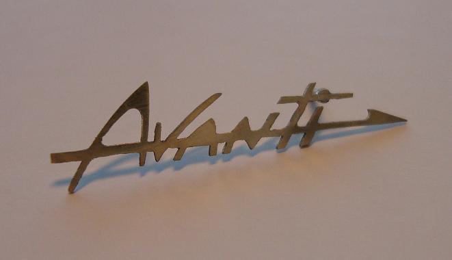
@ Detroit_Electric: Time is one of the few things nobody can buy! Thanks anyway to try to catch up. @ Spinneyhill: Probably during the patience distribution I was probably the last one in the row, and "they" still had a lot to distribute! August 29, 2008 Finally, it’s done ! I could pick-up the finished parts. They will be stored until their definitive installation. However, some will be installed without delay: the moldings for the door panels, the ash trays for the rear and other small parts. The costs ? About $ 50.00. If those parts would have been at scale 1:1, the costs would not be the same! This week, I began another large part: the name plate for the front end panel. This part is about 20 mm (0.8 ») in length; sorry, I forgot to use a coin for comparison). On a screen, this part is really rough but, seen in real life, the irregularities are not disturbing. This is one more part to be chromed! November 14, 2008 Another tree was just completed. Those parts will not be shiny but mat chromed. As you can see, there is the complete exhaust system together with the clamps; the clamps for the radiator hoses and the brake rotors, plus other small parts. The second picture from this tree is from the back side. For all those who not guess how all that is done, I’m showing my machine « park ». First, the lathe. It’s not a large machine, but ideal to machine the brass. Turning steel is already more difficult due to a lack of rigidity. The lathe is used a milling machine or press drill with few changes. Here too, the lack of rigidity is not ideal for some milling work; therefore just little metal is removed each time and there is a forced break to let cool the motor. Sometimes, a more robust machine would help a lot but for that I would need more space which I don’t have! My first machine was more primitive and rather “flexible”. This machine is used (at the time of the report) as a flexible shaft or to polish the parts to be chromed. The other tools I have: some files, a small vice, some watchmaker tools and some dexterity!


-
Roger's handcrafted 1:12 scale models
Roger Zimmermann replied to Roger Zimmermann's topic in Our Cars & Restoration Projects
August 05, 2008 It’s is time to build the windshield wipers! Those parts are really small: the first picture is showing it. At the right, a part polished, ready to be chromed. On the left, the various parts needed to do the other wiper: the arm, which is articulated and the wiper blade, articulated too. Both large parts are shaped like a U, but the section is not constant, which is common to each wiper blade. Each complete wiper has a weight of a third of a gram, not enough heavy to have any effect on the suspension! On the model, the wipers will be attached with a screw from the inside; therefore, they will not be movable; a spring will maintain them against the windshield. August 24, 2008 Details, details ! You can see on the picture the battery, similar to the ones installed on 1953 to 1956 Cadillacs, then two horns. On their right, the voltage regulator; down on the left the relay for the horns; the last part is the relay for the starter motor which is independent from the motor, like on the Ford (and others) products. I’m slowly coming to the end with the fabrication of the parts; soon all the assembled parts from the body will be removed to prepare it for the paint. The same process will happen to the engine and the frame. The first batch from the parts to be chrome dis not yet ready; I’m getting nervous!


-
Roger's handcrafted 1:12 scale models
Roger Zimmermann replied to Roger Zimmermann's topic in Our Cars & Restoration Projects
Chrome is expensive everywhere! In a usual situation, when you are taking a part to the plating shop, the part must be first "dechromed", then the cooper removed, usually mechanically; then the part is polished and go to various baths. In my case, the polishing is done; the plating company "just" has to degrease, put a flash coat of copper for adhesion and then chromed. I don't remember if my parts are first nickeled, but I doubt. For the batch in the above picture, the boss is asking CHF 50.- which is more or less $50.00. -
Roger's handcrafted 1:12 scale models
Roger Zimmermann replied to Roger Zimmermann's topic in Our Cars & Restoration Projects
July 18, 2008 No, we are not yet in December, but what I will show to you is similar to the Christmas tree: we have a frame and we put the shiny things on it! Most certainly you guessed that I'm writing about the parts from the Avanti model which will go to the plater. It would be too risky and tedious to give the parts individually, therefore they are arranged on a frame made with heavy copper wire. People who are building plastic scale model will understand as all the parts are grouped on a similar system; it was the inspiration to do the same. There are 56 parts on this tree; 3 parts do not belong to th Avanti; maybe some of you will discover which ones. This is only a part from the parts to be chromed. The next serie will include the bumpers, window frames and so on. I hope that all will go on that second tree. There will be a third one for parts having a dull chrome like the exhaust tubes, brake rotors and other small parts. The tree, pictured with a different position from the camera.

-
Roger's handcrafted 1:12 scale models
Roger Zimmermann replied to Roger Zimmermann's topic in Our Cars & Restoration Projects
Thanks Tom! For a while, I wrote nothing because I was busy with the planning of the V-16 Cadillac frame and engine scale model. As you see, there will be more to read! -
Roger's handcrafted 1:12 scale models
Roger Zimmermann replied to Roger Zimmermann's topic in Our Cars & Restoration Projects
Thanks Keith and Paul for the comments! The hood ornament is "very large": 1.22" x 1/2". -
Roger's handcrafted 1:12 scale models
Roger Zimmermann replied to Roger Zimmermann's topic in Our Cars & Restoration Projects
May 19, 2008 The jewellery There are just a few chromed parts on this vehicle; the hood emblem is one among them and its shape is particular. It seems easy to fabricate, but the difficulties are coming when starting the build! . Here it is, polished and ready to be chromed. The surface around the "S" will be black painted, like the real one which can be seen on the picture in the background.
-
Roger's handcrafted 1:12 scale models
Roger Zimmermann replied to Roger Zimmermann's topic in Our Cars & Restoration Projects
April 24, 2008 It’s not a surprise that my question stayed unanswered! The strange part is the inner molding assembly with the overhead switch module. It’s not the nicest part of the model but will be hardly visible. The sunvisors can be lowered, as you can see. The leather on the frame is not yet glued ; it will be done at the final assembly. After the windshield molding, I did the rear ashtrays. They are not large : the outer frame is measuring 6 x 5mm. They are polished, ready to be chromed. The cover can be opened, of course.


-
Roger's handcrafted 1:12 scale models
Roger Zimmermann replied to Roger Zimmermann's topic in Our Cars & Restoration Projects
People, thanks for all the "like" you are attaching to my various posts, I do appreciate that! It means that some folks are still following my adventure with small cars. March 09, 2008 Here we are ! the almost finished door panel is on the first picture. Missing are both moldings and the locking lever (wich is not functional). Those parts must be chromed first. The door’s bottom is not ready either : the carpet (velvet) is not yet glued. This will be done at the final assembly because the velvet is attracting the dust I’m producing in quantity. Now, I can do the other side. When all parts will be ready, all will be removed for the paint preparation. April 06, 2008 What is that strange part on the second picture ? a misrepresented elk ? Yes, this part will go into the model ; two accessories are missing. If they were there, the answer would be evident. On the real car, this is covered with vinyl. On the model, I will use some leather because of the thickness.

-
Roger's handcrafted 1:12 scale models
Roger Zimmermann replied to Roger Zimmermann's topic in Our Cars & Restoration Projects
March 05, 2008 As the hardware is ready, it's time to go to the software. Oups! to the upholstery. I'm showing how the "stitching" is done. On the brass basis, I'm gluing strip of leather, 0.5mm thick, with just enough space between each strip (first picture). The upper molding is there as a guide, the strips are not going under the molding. All strips are glued on the second picture. I can begin with the skin wich is a 0.1 to 0.15mm thick leather. If something is going amiss, I will have to begin from zero. I'm pushing the leather between each band, one after the other; therefore, it takes a rather long time for one panel. With some luck and not too many difficulties, the first door's panel is ready. The arm rest is screwed from behind; it helps to keep the leather at its place. The lower part will be cover with velvet to simulate the carpet; the excess leather will be cut when the glue is set, after about 24 hours. The next step: to cover the padded part with the fawn leather. Here, I will be able to stretch the leather to get a pleasant structure.


-
Roger's handcrafted 1:12 scale models
Roger Zimmermann replied to Roger Zimmermann's topic in Our Cars & Restoration Projects
February 09, 2008. Tensioner or not ? As some little changes were needed, I had to cut the string to remove the window. Once the repairs done, I did the same number of turns with the new string on the drum to raise the window as to the drum to lower the window which I did not the first time. I gave a good tension on the string before I did the knot to attach both ends and I noticed that the tensioner was no more needed. I played a lot with the window until the shaft from the drum almost seized into the bearing! It was gradually more and more difficult to turn the handle till I understood that a drop or two of oil would not harm. Once the situation coming back to normal, I let the assembly alone. It will be good for the next 40 years ! February 29, 2008 That bitch of left window gave me a lot of trouble. The window was jamming, the string broke, the handle was turning with difficulties; I had a lot to do to save the situation. Curiously, the RH side went without any difficulty. It seems that now everything is under control and I can go further. To hide that mechanism, a door panel is needed. I used a 0.3mm sheet of brass; the padding at the top of the panel is done with a two components filler. The various bits of leather were needed to get the proper alignment of the lock escutcheon. This part is attached to the door’s panel with 2 screws. (first picture) The final trim will be glued on this base. I have first to do both horizontal moldings, the one located between the fawn and blue leather; the other molding is between the blue leather and the carpet at the door’s bottom. The armrest is not yet finished; there is still plenty of work ahead! A detail of the lock, with the strange looking escutcheon. (second picture) A view from the other door, without the arm rest I could rescue and modify from the original model.


-
Roger's handcrafted 1:12 scale models
Roger Zimmermann replied to Roger Zimmermann's topic in Our Cars & Restoration Projects
No, I think I will continue with the same thread. However, I'm not that far! I will have to finish the Avanti story first. Right now, I'm doing some scale drawings for the frame. Nothing yet to be published. -
1961 Mercury Meteor 800 restore
Roger Zimmermann replied to Laughing Coyote's topic in Our Cars & Restoration Projects
That's bad place for welding! I hope that you don't have too much warpage at your rear fenders! -
Scale model 1932 Cadillac V-16
Roger Zimmermann replied to Roger Zimmermann's topic in Cadillac & LaSalle
Perfect Alex! I do appreciate a lot. Anyway, it's all the time better to do pictures on a clean/painted part, but I had not the choice!


