


Roger Zimmermann
-
Posts
3,098 -
Joined
-
Last visited
-
Days Won
24
Content Type
Forums
Gallery
Events
Everything posted by Roger Zimmermann
-

Roger's handcrafted 1:12 scale models
Roger Zimmermann replied to Roger Zimmermann's topic in Our Cars & Restoration Projects
@ JamesR: yes that hand brake lever is working as intended; my goal is that the brakes are functioning on all four wheels with the main brake pedal or to the two at the rear with the hand brake lever. Totally futile, but I like it! @ Pat: certainly the files are not the same, try smaller ones! -
Roger's handcrafted 1:12 scale models
Roger Zimmermann replied to Roger Zimmermann's topic in Our Cars & Restoration Projects
It seems that my hand brake picture was well received! Before I began with the complex casting supporting the brake and clutch pedals (for which Alex sent me critical dimensions, thanks again Alex!), I did both covers which were missing: the one for the idle gear and the one for the clutch ventilation. Now I can, with the help from many pictures, design that support attached to the transmission.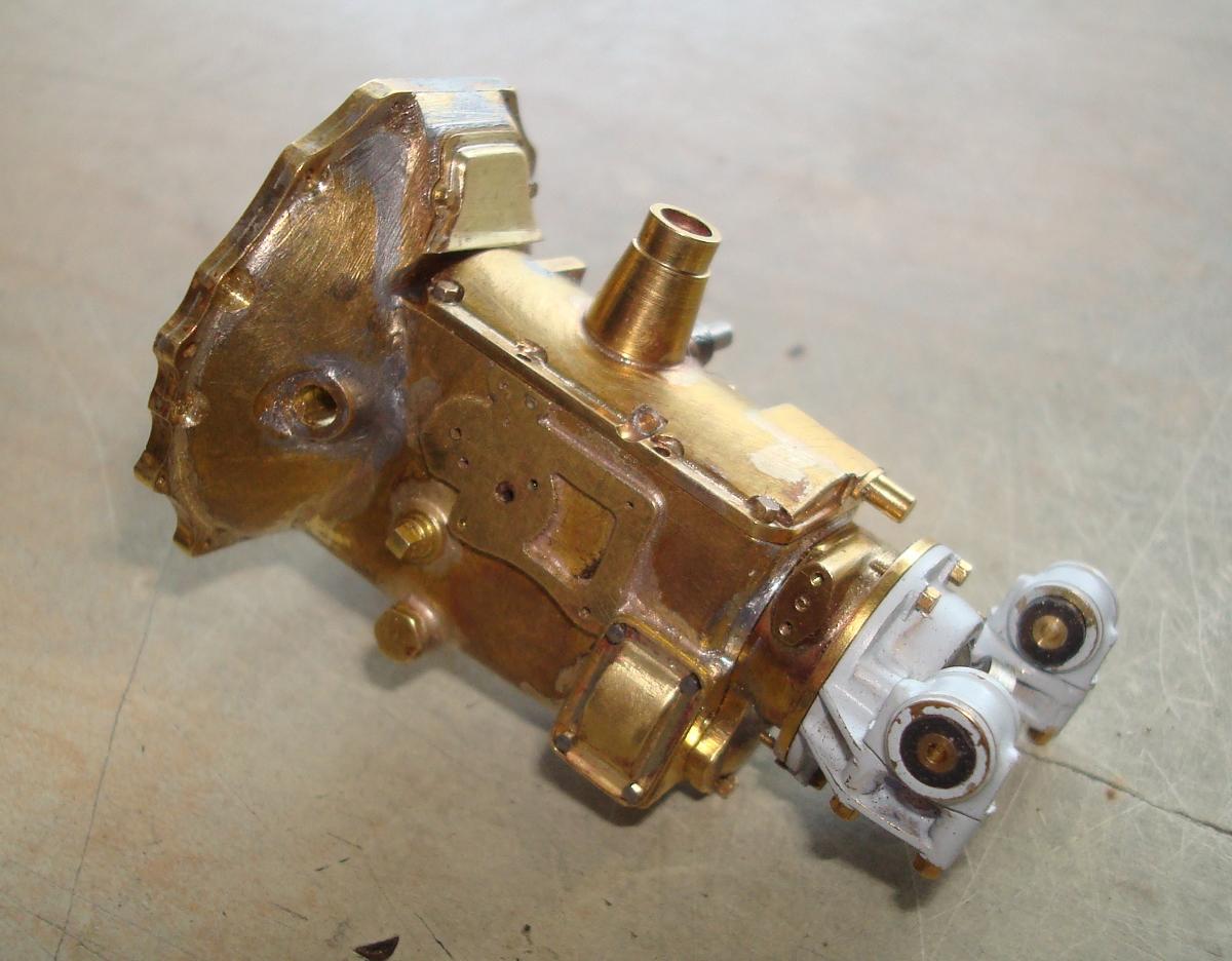
-
V-8, V-12 and V-16 engines from Cadillac built at the same frame time are very similar. When I'm looking here at the Lincoln engine, I'm wondering if the same engineers designed the Lincoln and Cadillac engines!
-
Roger's handcrafted 1:12 scale models
Roger Zimmermann replied to Roger Zimmermann's topic in Our Cars & Restoration Projects
A tiny spring...No rocket science, isn't it? Well, if only I would have fingers' size in relation to the spring! It went twice in the air, found it on the floor both times, a luck! Now, the hand brake lever is functional; I hope that after the plating (only the tiny rod is painted), there will be enough play at the handle and pawl to let the spring doing his job, because his strength is rather limited! I will go now to the other side of the transmission: one cover must be done plus the brake and clutch support which is bolted to the transmission. I think I will need again the help from Alex for the location of the pedals... Don't look too much at my nail: it get sometimes caught by the files as fingers are sometimes the best vice!

-
Roger's handcrafted 1:12 scale models
Roger Zimmermann replied to Roger Zimmermann's topic in Our Cars & Restoration Projects
Thanks! To set the parking brake, you pull the lever towards the seat. -
Roger's handcrafted 1:12 scale models
Roger Zimmermann replied to Roger Zimmermann's topic in Our Cars & Restoration Projects
Only a small detail is missing; otherwise, the hand brake lever is complete. What's missing? A tiny spring which is located between the movable handle and the fixed one. With the spring, the pawl is pushed down, securing the lever when the hand brake is activated. As you can see, the rod is screwed into the trunnion. I wanted to skip that complication, but I quickly realized that this is need, otherwise the rod cannot be inserted into the guide near the pivoting point.
-
Roger's handcrafted 1:12 scale models
Roger Zimmermann replied to Roger Zimmermann's topic in Our Cars & Restoration Projects
Thanks Randy! Do you know why most of the modelers don't go that far into the details? They don't have the time; what they are beginning should be ready the next day! -
Roger's handcrafted 1:12 scale models
Roger Zimmermann replied to Roger Zimmermann's topic in Our Cars & Restoration Projects
It seems that my expectation about a workable hand brake will come to reality. I did the pawl, out of steel as brass may be too weak. Indeed, I made two pieces. As the first one did not please me, the second one was refined, somewhat shorter and the geometry modified a bit. When the lower part of the hand brake lever will go to the left, the pawl is preventing the movement. On the contrary, the pawl allow the movement and the hand brake can be set without using the handle at the top of the lever, which will be done shortly. The hole on the lever just above the pawl is for the rod actuating the rear brakes. Thanks to Alex D., I modified the handle of the lever. My estimated dimensions were way too generous. Alex measured the assembly from his car and submitted a nice drawing with legible dimensions. The handle seen on the picture is half way between my estimates and Alex's dimensions. As brass is not the strongest material (and I cannot do the lever in steel), I will probably choose a compromise between reality and something stronger. Thanks Alex!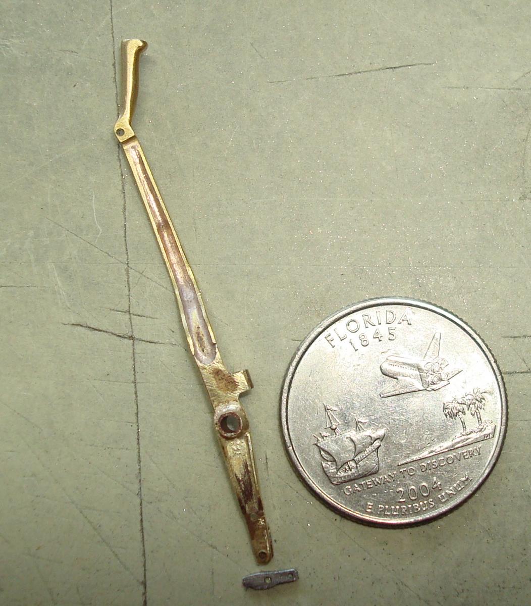

-
Roger's handcrafted 1:12 scale models
Roger Zimmermann replied to Roger Zimmermann's topic in Our Cars & Restoration Projects
Thanks for the comments! Another small item added: the ratchet for the hand brake. At first glance, it's an easy part, but not for a model. First, I wanted to have it wide enough for strength, but the starter motor said no: I'm too close. The plan B was to have a thinner plate to satisfy the starter motor and a wider element with the teeth. But, how to do the teeth? On my basic machine, I cannot mill a curved segment and be sure that the distance between teeth is the same. As I intended to do the part in two pieces, the solution was easy: to mill the teeth on a straight piece with a 60° milling tool and then to bend the segment to soft solder it on the base. I have now to do the pawl; if my construction will work as intended is totally unsure. If I have no success, that will be just decorative and not functional.
-
Roger's handcrafted 1:12 scale models
Roger Zimmermann replied to Roger Zimmermann's topic in Our Cars & Restoration Projects
The hand brake lever is looking a lot like a sculpture from the Swiss Giacometti, but has no value compared to his "marvels"! For the moment, there is just the profile from that lever and the lower part is far from finished: there will be a fork for the pawl. I will first doing the upper part and then the lower one. On the real car, this lever is about 20" tall from the axle to the end...Imagine that is a car from today!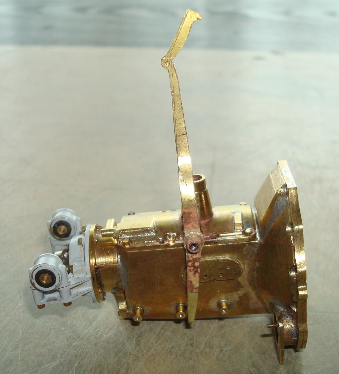
-
Roger's handcrafted 1:12 scale models
Roger Zimmermann replied to Roger Zimmermann's topic in Our Cars & Restoration Projects
Sometimes, I'm wandering from one element to another one, without relation between both. After the frame was ready, I was faced with the same question: and now? There are still hundreds of parts to be made, the choice is large enough! This time, I decided to finish one element: the transmission. The closing cover was just not yet done, not a big deal. This small part let me do many errors by not paying attention at what I was doing. I first did the flat part from the cover with a thick brass plate. Easy. Then I did the holes for the screws. As the location for the holes is done just with a rule, they are not perfectly spaced/aligned and I know that. With the flat element ready, I used it to drill the holes into the transmission's case. This implied that just one position of the cover's base would be right. When I silver soldered the curved part on the base, I managed to flip it over; in other words, I soldered the next part on what should be the surface contacting the transmission's case. Result: the hole were no more perfectly aligned. I enlarged 3 from the 6 until I could insert the screws. Then it was time to make a large hole in the curved part for the shift lever "tower". The position of it is not in the middle and here, I managed to do it at the wrong end! I had to enlarge more holes to be able to screw the cover...Fortunately, the bolt's heads are large enough to cover the holes... The remaining elements were added without problem. One of them is the shaft for the hand brake. The small cylinder at one end is representing the switch for the back-up lamp. The hand brake lever is therefore part of the transmission... I will continue with that. This is a monstrous lever half meter long which recall me the brake lever the "driver" from the cable cars in San Francisco are using, at least is what I saw in the seventies.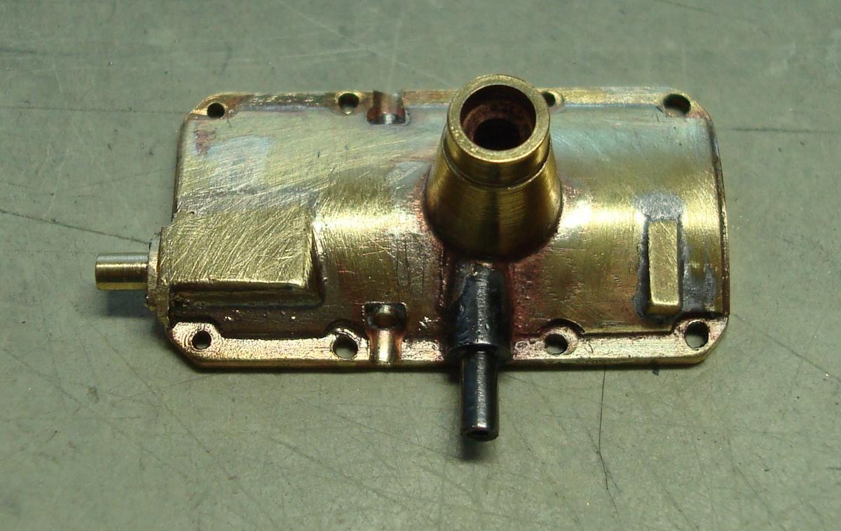

-
Roger's handcrafted 1:12 scale models
Roger Zimmermann replied to Roger Zimmermann's topic in Our Cars & Restoration Projects
Pat, you certainly know that I cannot build a scale model without functioning elements! Sure, the steering box will be added as well as the column and wheel. The hand brake will come maybe soon as I'm doing right now the cover for the transmission. You will ask: what is the relation? Well, the shaft for the hand brake is part of that cover. Clutch and brake pedal will be added; the goal is that the brakes at each wheel will be functioning. We'll see once if I'm too ambitious or not... -
Years ago, I had thousands owner's manuals, catalogs and shop manuals for GM vehicles. For 3 or 4 years, I sold the whole inventory to a man in Germany. Yesterday, by searching something else, I found some Chevrolet leaflets. Why did they not go to Germany, I don't know. Here is what I have for sale: Folder 1960 Chevrolet Corvette 1960, 8 pages, 12.8" x 5", $ 15.00 or best offer Leaflet 1960 Chevrolet, all models, 8 pages, 10.6" x 6.9", $ 10.00 obo Leaflet 1964 Chevrolet Chevelle IN FRENCH, 14 pages, 11.4" x 8.7", $ 10.00 (Only one available) Leaflet 1966 Chevrolet, all models, IN FRENCH, 12 pages 8.3" x 11", $ 10.00 obo Color card 1968 Chevrolet, 8.7" x 3.5", $4.00 obo All prices are without shipping charges. PayPal is welcome.


-
Roger's handcrafted 1:12 scale models
Roger Zimmermann replied to Roger Zimmermann's topic in Our Cars & Restoration Projects
Pat, something is missing on my parts: the thing to put the grease. I still don't know if I will ad them; there are maybe about 60! Anyway, thanks for your comments. Finally, the frame is ready: I fabricated the supports for the transmission and silver soldered them to the second cross member. With that done, it was rather easy to put the cross member into the frame (thanks its elasticity, I had not too much trouble to insert and remove it several times times) and soft soldering it. The rivets are not yet in place as you can see. The rubber bushings at the rear transmission was a wise decision, with my construction's variations, the holes in the supports are not perfectly aligned with the bushings. That second cross member is giving a significant torsion's resistance to the frame, but I'm sure that those frames are not very rigid and the road behavior was certainly miles away as what we have today. As almost all cars were made is a similar fashion, it was considered as "normal".
-
Roger's handcrafted 1:12 scale models
Roger Zimmermann replied to Roger Zimmermann's topic in Our Cars & Restoration Projects
With a lot of guessing and silver soldering, the brackets for the rocker shafts are done. I also added the thread to attach the exhaust support. My first guessing was not right, the first shaft was too near from the cross member (or the shape from the cross member is not quite correct). I had to tilt up the special tool and add a spacer on the bracket's flange. With that, the second shaft was much too high (it would have been above the frame); I had to modify the tool to have it at the "right" place. Then the job was cut, adjust, solder, let cool to handle it, verify that both shafts are still free and so on, and so on. There are still two holes at the cross member to be drilled; they could be done with the cross member installed in the frame. The holes are for the brake booster bracket; I'm sure it's better to drill them when I have the lateral position of the booster.


-
WTB 1962 Buick Special front lower suspension arm
Roger Zimmermann replied to Roger Zimmermann's topic in Buick - Buy/Sell
Thanks Auburncoupe for the good part which arrived recently! -
WTB 1962 Olds f-85 front lower suspension arm
Roger Zimmermann replied to Roger Zimmermann's topic in Oldsmobile - Buy/Sell
The parts arrived to the customer, in good condition. Thanks Auburncoupe! -
Roger's handcrafted 1:12 scale models
Roger Zimmermann replied to Roger Zimmermann's topic in Our Cars & Restoration Projects
Well, maybe some had a sleepless night not knowing what I intended to do. The solution is here: it's a special tool combined with an element which will be used. The picture below is giving some light, as well as a picture from the real bracket for the rocker shafts. For a long time, I had no idea how I could position in the air a bearing, a flange and the links attaching them. Not only both brackets should be identical regarding the position of both bearings but the rocker shafts must move without binding. The solution I found was to make a long strip with both flanges, add on that strip two brackets to held the shafts at the proper distance. When the brackets will be ready, the excess material will be removed.

-
Roger's handcrafted 1:12 scale models
Roger Zimmermann replied to Roger Zimmermann's topic in Our Cars & Restoration Projects
As I would like to have operative brakes (a dream from youth: when I first began my Avanti model, I wanted to have...hydraulic brakes. I did not even had a lathe then. Needless to say, they were stillborn), the system must be reproduced as well as possible. However, if you are looking at my own picture, it does not look like the original system. What am I trying to do? I'm attaching also a picture from a real chassis. The answer soon!

-
Sgt.John 1956 Buick 4d Hardtop
Roger Zimmermann replied to Specalist John's topic in Our Cars & Restoration Projects
Sorry for your father. Maybe he is looking from above what you are doing... -
Sgt.John 1956 Buick 4d Hardtop
Roger Zimmermann replied to Specalist John's topic in Our Cars & Restoration Projects
At the end, you will love the rust! -
Roger's handcrafted 1:12 scale models
Roger Zimmermann replied to Roger Zimmermann's topic in Our Cars & Restoration Projects
That second cross member took a long time to build. And sometimes I'm not very productive...Also, it's always a bit difficult to show something at the "right" moment; some may be bored to see some brass bits before the part is looking the way it should. Now I can show it and the way it will be in relation to the transmission: I "just" have to add the brackets to the cross member! You'll probably noticed that the supports at the transmission have bushing made with rubber, more or less like the original. The goal here is not to avoid to transmit vibrations to the frame but to facilitate the installation of the bolts as the bushing/brackets may not align perfectly. The cross member is also not yet ready to install in the frame: the brake system is attached to it. I have to begin the supports for the actuating tubes; once the supports can be screwed on that crossmember I will solder it to the frame. After that, any drilling at the front or rear will be impossible. Therefore a good planning is the key to the lack of failure!
-
my 1966 Special rejuvenation
Roger Zimmermann replied to SpeedyBuick's topic in Our Cars & Restoration Projects
Nice underbody! -
Roger's handcrafted 1:12 scale models
Roger Zimmermann replied to Roger Zimmermann's topic in Our Cars & Restoration Projects
Thanks Mike! I'm glad I can do something for you... -
It's incredible how unprecise the various elements were welded together. That truck is now better than new...


