RichBad
-
Posts
740 -
Joined
-
Last visited
-
Days Won
1
Content Type
Forums
Gallery
Events
Everything posted by RichBad
-
Thanks - any particular sanding sealer?
-
1927/28 Dodge Brothers series 128/129 Tourer
RichBad replied to RichBad's topic in Our Cars & Restoration Projects
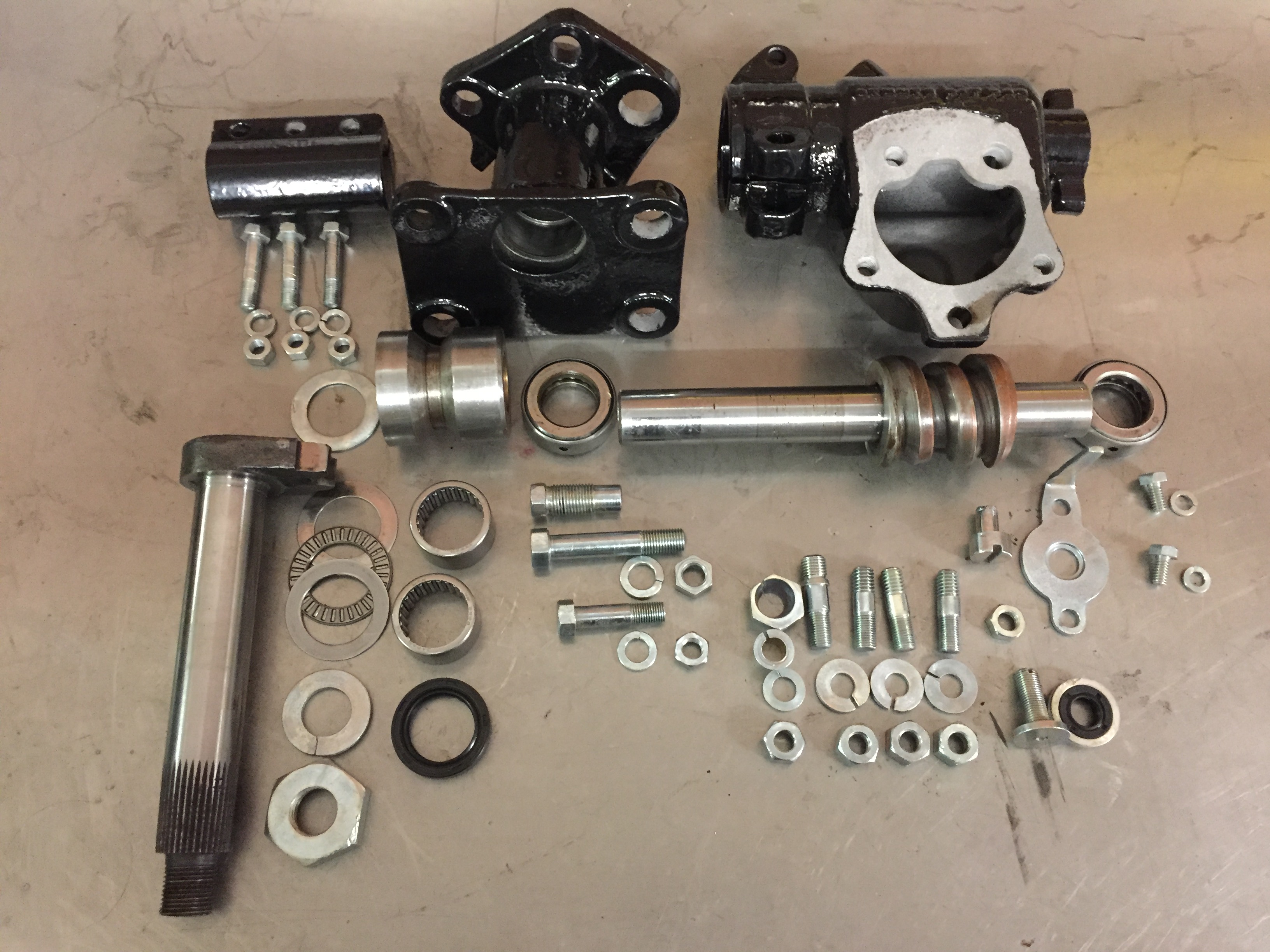
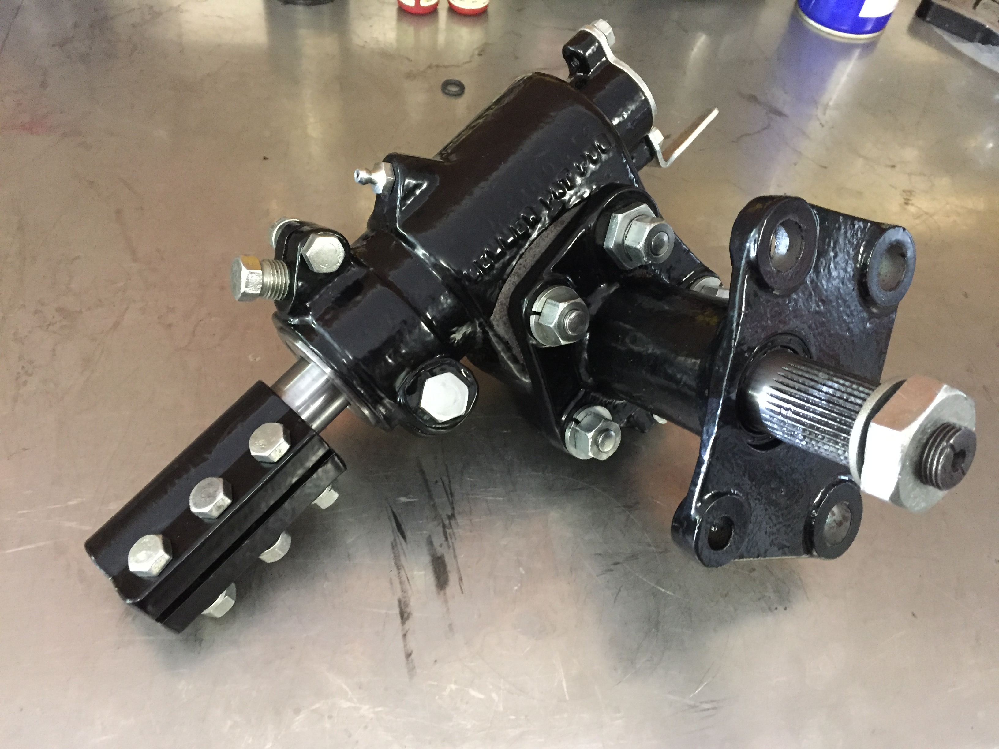
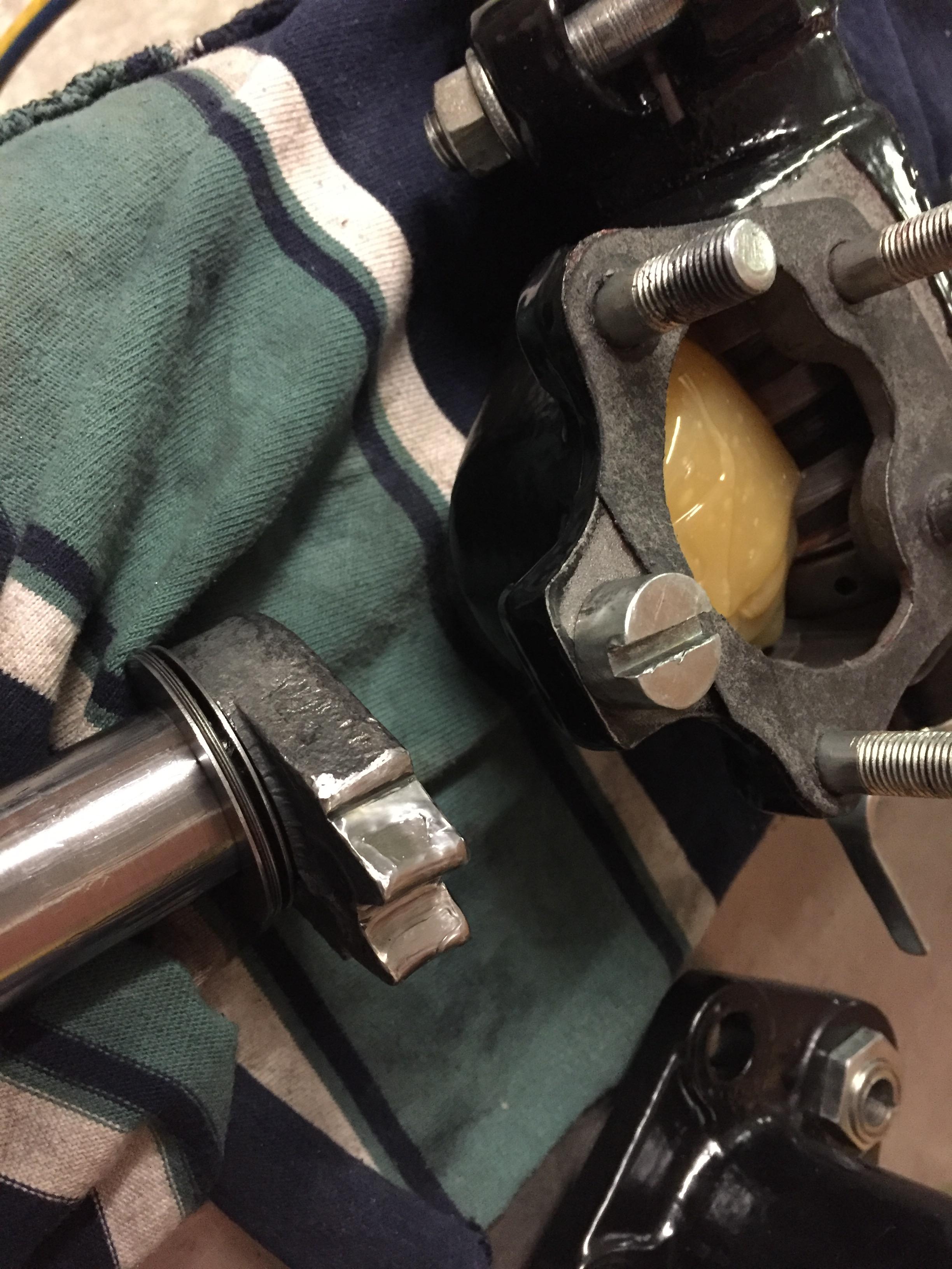
Steering box. Modified with roller bearings on the sector shaft and modern oil seals on the input, sector shaft lower end. Cleaned up the sector shaft teeth to remove play and provide even contact - took about 10 hours of grinding, polishing assembly and disassembly to get it just right. Filled with semi fluid grease.


-
1927/28 Dodge Brothers series 128/129 Tourer
RichBad replied to RichBad's topic in Our Cars & Restoration Projects
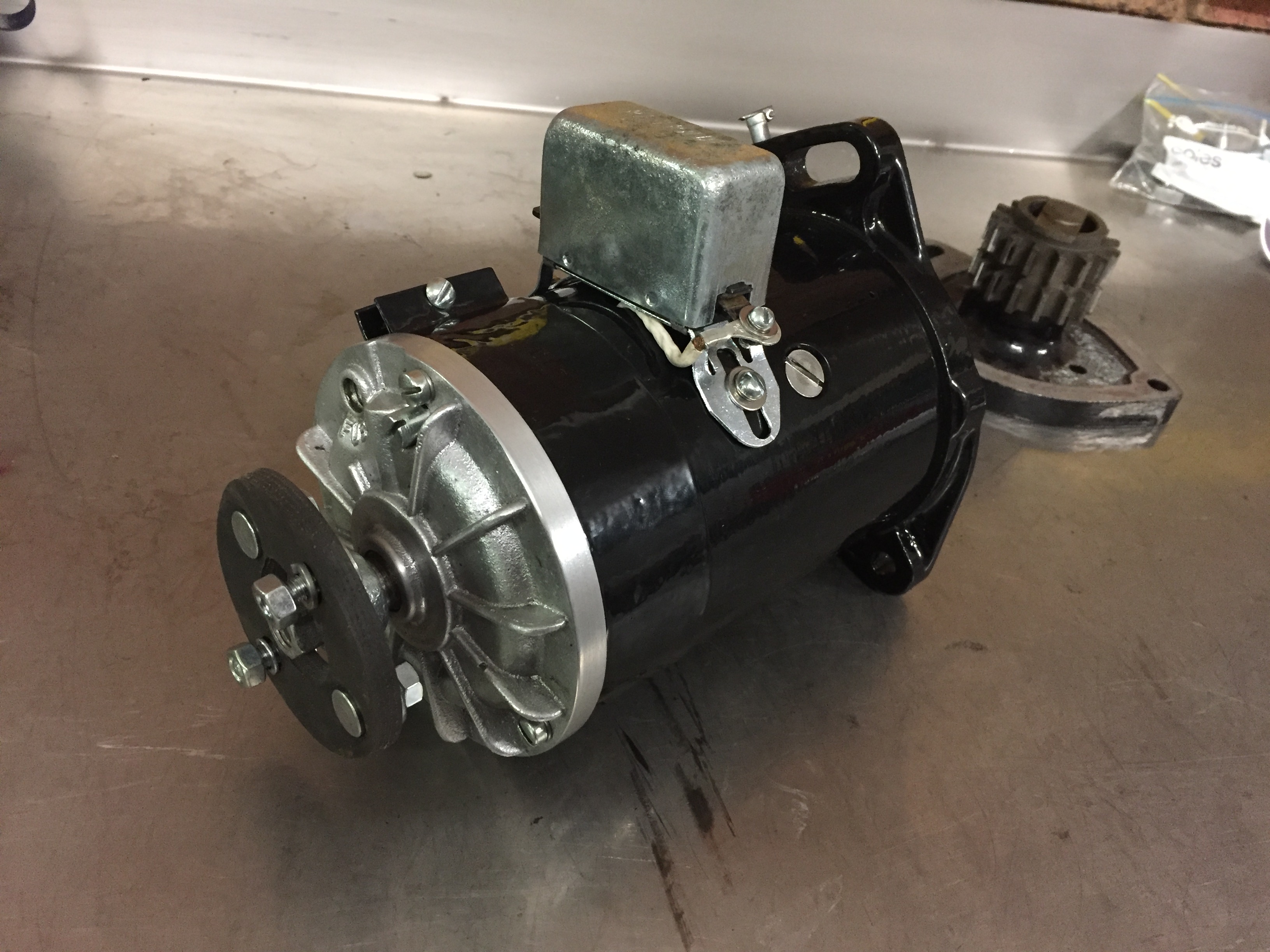
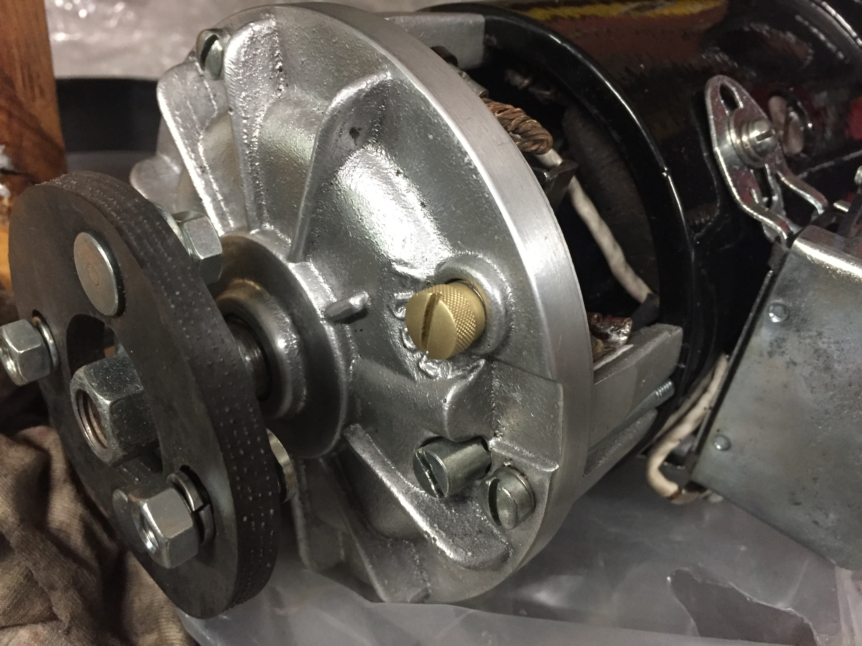
Generator/dynamo done, just needs the fuse holder and replacement nameplate ( original was a bit of a mess). Got a fuseholder - pic below if anyone was wondering what it looks like


-
How to remove 927 Dodge Steering Wheel
RichBad replied to NZStuart's topic in Dodge & Dodge Brothers
I thought a loose nut behind the wheel was a pre-requisite for Dodges Sorry - Dad joke! -
Hi, Can anyone recommend the best option for finishing wooden spoked wheels? I’ve completely stripped my wheels and powder coated the hubs and rims. I wanted to finish the spokes in their natural colour and want something that is tough and will last! Something that can fill the grain would be ideal as a few of the grains have ‘opened’ slightly. Looking around the web there seem to be recommendations for and against almost everything therefore I’m looking for what people have tried and tested (with good results)! thanks!
-
1927/28 Dodge Brothers series 128/129 Tourer
RichBad replied to RichBad's topic in Our Cars & Restoration Projects
Modern seals for the rear diff with machined adaptors to fit them to the existing felt retainers.


-
Thanks! 1927 series 129. Not having a drain hole sounds like fun!
-
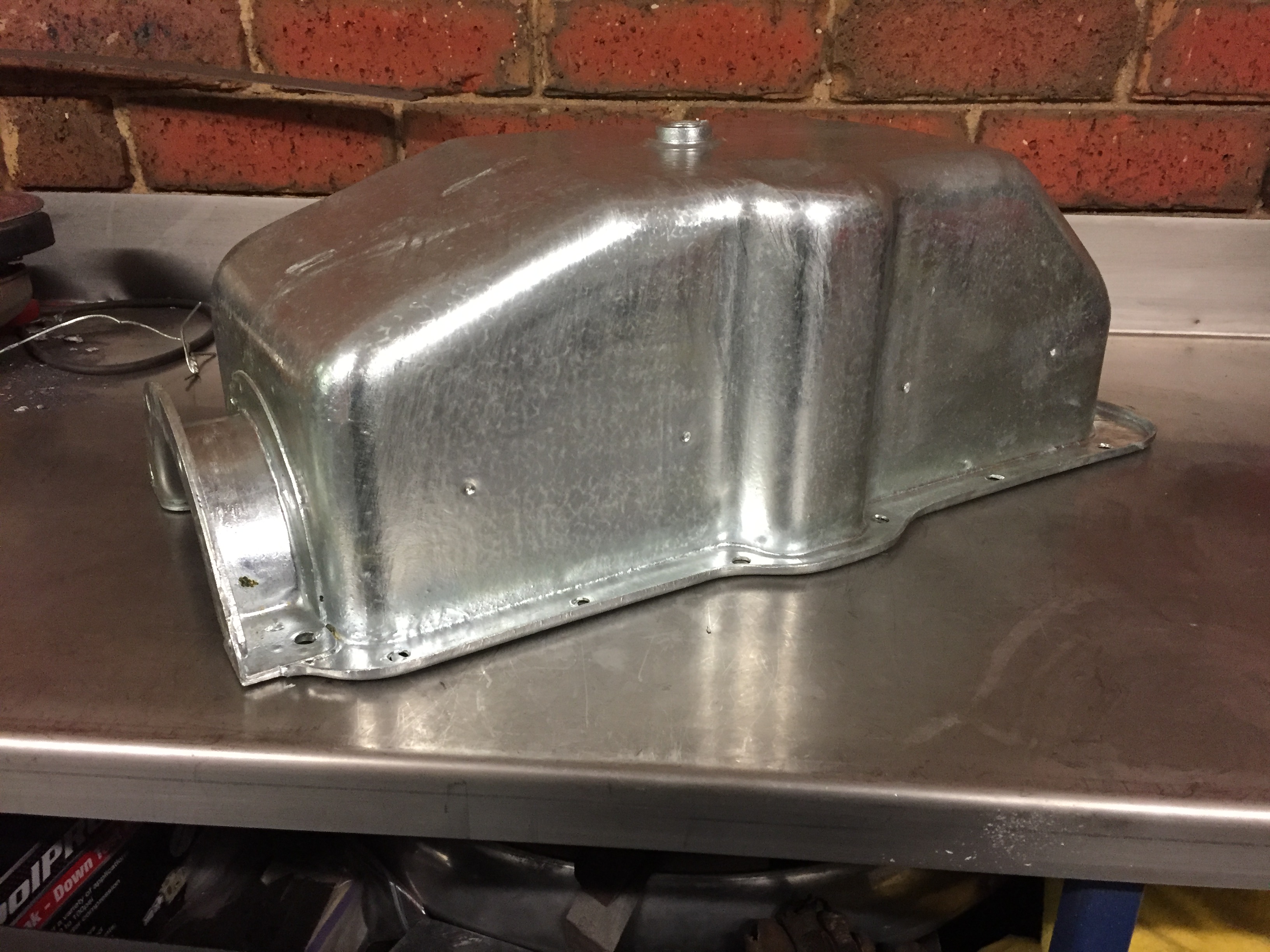
OK, I decided to go for it and get my sump hot dip Galvanized and it came up pretty good and was easier than I thought it would be. I first removed the inner oil tray that was riveted in as it wasn’t plated originally and I didn’t want it to distort (also needed it out to clean out the sludge). The front flange, rear flange/inserts, the rear drain pipe and drain plug insert were all soldered however, after removing all the solder only the rear drain tube could be removed. The drain plug insert was swaged in (after galvanising) with solder to seal. The front flange looks like it was spot welded (probably before plating) with the solder to seal/fill the gaps. The rear flanges looked like they were also spot welded but possibly after the plating (as they didn’t look like they were plated originally). I was planning on re-sealing the flanges with solder but the galvanising seems to have filled/sealed the joints very well. front flange rear flange/insert


-
1927/28 Dodge Brothers series 128/129 Tourer
RichBad replied to RichBad's topic in Our Cars & Restoration Projects
Sumpback from Galvanisers, came up pretty good. Had to remove the inner oil tray and drain tube from the rear (they were not plated originally) otherwise it was easier than expected!


-
1927/28 Dodge Brothers series 128/129 Tourer
RichBad replied to RichBad's topic in Our Cars & Restoration Projects
Thanks! Mine is a tourer and the door handles are quite different. -
1927/28 Dodge Brothers series 128/129 Tourer
RichBad replied to RichBad's topic in Our Cars & Restoration Projects
Thanks - I think the frame may be quite similar. Do you have any photos around the front cross member showing where it meets with the main frame? Thanks -
1927/28 Dodge Brothers series 128/129 Tourer
RichBad replied to RichBad's topic in Our Cars & Restoration Projects
That's a big screen - what's the purpose of the metal shield around the outside of the screen - does it help stop oil surge? -
1927/28 series 128/129 Fast Four frame/chassis
RichBad replied to RichBad's topic in Dodge & Dodge Brothers
Another weekend with the grinder - we’ll and truly had enough of metal filings! Pretty much cleaned out all the previous ‘repairs’ now. Should be a lot lighter! Front engine mounts also had some bad repairs so removed them from the cross member to fix up. There was a lot of weld to cut out! Rear engine mounts had also been caught up in previous weld repairs so removed them too. The frame was bent up and inwards from just behind the rear mounts so have to straighten that too (assuming the rails should be straight along the length). Ready so start fixing pieces back in place - need to get some dimensions first before I start welding - help!


-
1927/28 series 128/129 Fast Four frame/chassis
RichBad replied to RichBad's topic in Dodge & Dodge Brothers
Had a couple of questions before I start putting the front end back together. 1. Is the chassis outer face a straight line from front to rear spring mount? 2. Should the chassis top edge be straight from the rear cross member to the steering box front mount holes? 3. Where the front chassis top edge starts to angle up (from just in front of steering box) is it a straight line to the front cross member? thanks! -
1927/28 Dodge Brothers series 128/129 Tourer
RichBad replied to RichBad's topic in Our Cars & Restoration Projects
Shackles all finished. Rebored and bushed to take out the wear, zinc plated and painted. Thanks to Bob B for the parts, they look a bit different now:)
-
1927/28 series 128/129 Fast Four frame/chassis
RichBad replied to RichBad's topic in Dodge & Dodge Brothers
Yes, it works quite well but the bit I’ve been having difficulty with is holding tight from the other side whilst using the air hammer. -
1927/28 series 128/129 Fast Four frame/chassis
RichBad replied to RichBad's topic in Dodge & Dodge Brothers
Had enough of grinding so thought I’d move to something constructive and repaired the rear spare wheel mounts and re attached to the chassis. First attempt at riveting, not as easy as I thought but getting better the more I do.

-
This may help with details of the carb

-
Agree with the others, does sound like fuel shortage. Could be supply to the carb or carb its self. Supply to the carb can be checked quite easily (either by disconnecting at carb or by using a separate tank temporarily). For the carb, check the fuel float needle is moving correctly (should be down when the float bowl is full and then move up as the level drops, it could be sticking). It could also be running too rich -OK for starting but then fouls the plugs and takes time to 'dry out' before it will re-start. Less likely though and I don't think these engines are too fussy about running rich. Are you using the choke at all? The butterfly valve at the top is the throttle valve so sounds like you have your linkage correct. The lever at the bottom is for the fuel mixture (effectively the choke).
-
Perfect, thanks Bob
-
Thanks Bob. Do you know what thickness should be on the front of the diff? I guess the thickness is less critical (as the pinion to gear mesh has to be set anyway) but it would need to be quite hard so it doesn't compress over time. Something similar to the ones on the engine front mount and timing cover? Thanks, Richard
-
1927/28 series 128/129 Fast Four frame/chassis
RichBad replied to RichBad's topic in Dodge & Dodge Brothers
A weekend with the grinder (whoever repaired it last liked weld). Have the cross member separated from the sides. Cross member not too bad but needs some repairs to the mounts. Have cut a repair piece for the sides, next step is to cut out the vertical section of the sides to fit the new section (and clear out more weld).


-
Thanks, I got it down to 0.002” endplate on the gear - hopefully that’s ok.
-
1927/28 Dodge Brothers series 128/129 Tourer
RichBad replied to RichBad's topic in Our Cars & Restoration Projects
Oil pump finished - picked thinnest gasket possible, resulted in ~ 0.002” end float on the gears. Anyone know what the front pipe is for - it just feeds to the other side of the mesh (bypassing the filter). I guess it was a crude bypass if the mesh becomes completely clogged - but if it got to that stage then the oil that it would be picking up wouldn't be great!
-
Olsen didn’t have anything listed for the early ones. I can make them easily enough from sheet just wanted to make sure I get the right material/thickness.