


Oregon Desert model 45
-
Posts
1,154 -
Joined
-
Last visited
Content Type
Forums
Gallery
Events
Everything posted by Oregon Desert model 45
-
The components that drive the oil pump in my 1924 6 cylinder motor have heavy wear on contact surfaces transmitting torque. is this normal ? Perhaps someone filled the motor with a heavy grade of oil which strained these oil pump drive components and caused this wear ? The pin inside 41476 oil pump shaft coupling assembly is worn so much that i am concerned it could shear off, resulting in complete loss of oil pressure to bearings and rockers. I plan to replace this pin. One component which wears independantly of torque is the brass oil pump base plate. Both gears sit on this plate and rub as they rotate, slowly wearing into the brass. This one has a relatively light amount of wear, suggesting low mileage on the oil pump. The next component ready to fail in the oil system was the pressure relief valve in the the oil distribution manifold. It's a very simple valve with a small plunger blocking a relief port with a spring to hold it closed. A surge in oil pressure will overpower the spring force, causing the valve to open and spill oil out the side of the valve body to relieve the pressure. When i opened up this valve, the spring was in about 12 small pieces. There would have been no oil pressure the first time the motor was started. Water in the oil caused the spring to rust and break into pieces. The final failure probably already happened long ago. There is smaller tube inside the crank case which supplies oil to the pressure gauge, and rocker arm assembly. Some of that oil returns by running down the push rods and dripping onto the cam rollers. This line was plugged and required over 60 psi air pressure to clear the blockage. When my father bought this motor it was disassembled, and the cam was deeply rutted where the roller lifters make contact. A complete loss of oil to the rockers and rollers could explain why the cam was severely worn. Any motor that has been sitting for decades without running should be opened up and the entire oil system checked out for such issues before starting. Now to explain why the main bearing oil pipe assembly is completely disassembled. One of the soldered joints had broken off at a "T". I applied some heat at the T, and goop inside the tube turned into liquid and starts to pour out. Has anyone ever try to solder a joint that is not completely clean ? it won't stick. So i tried to disassemble the T to get access to the insides to clean by heating and twisting, broke the main pipe, and now have to make a replacement. Kevin


-
 Reposted from Craigslist NOT MINE 1932 buick engine and transmission parts - $90 (vancouver,wa) http://portland.craigslist.org/mlt/pts/5626130013.html 32 buick series 60 engine parts with transmission and clutch
 -
Reposted from Craigslist. NOT MINE 1923 Buick 4 cyl roadster pickup converted from a roadster https://jerseyshore.craigslist.org/cto/5595691367.html


-
1924-45 Rear Seat Courtesy Light Removal
Oregon Desert model 45 replied to 27donb's topic in Buick - Pre War
Hi Don. those dimensions will help me a lot. There are 2 more dimensions I should be checking to be sure the body hasn't bowed in or out in the middle. Can you measure the body width in the rear door opening right behind the front seat at the door sills, and another measurement of body width at the top of the center pillar. I really appreciate the help Kevin
-
1924-45 Rear Seat Courtesy Light Removal
Oregon Desert model 45 replied to 27donb's topic in Buick - Pre War
Don many thanks for these photos I have a big favor to ask. can you please make the measurements that I marked up on your photos ? I have spent many hours pouring over photos and working on mocking up this seat wood for my model 45, and these measurements will help a lot. Kevin BCA # 47712


-
1925-1926 Oldsmobile hood. good condition. $150 location Portland Oregon


-
1924-45 Rear Seat Courtesy Light Removal
Oregon Desert model 45 replied to 27donb's topic in Buick - Pre War
Don Terry is correct - that does look like a snap ring holding the lens in. Here is a photo of the light housing, which is screwed to a block of wood on the seat back from inside the housing. Pull up the front seat cushion and the wire should be visible somewhere back underneath. Also when you have the cushion out, can you get some photos of the front seat wood platform for me ? I am still trying to figure out all that wood underneath the seat. Kevin
-
wood assembly and gluing - 1925 Buick
Oregon Desert model 45 replied to Hubert_25-25's topic in Buick - Pre War
Hugh I have a theory about the 1/4" strips under the sills. Wait until all the sheetmetal has been tacked in place, and then try sliding the strips in and fasten them after everything else is lined up. This should make it easier to fit the rear tub sheetmetal over the wood frame since the sheetmetal wraps over the upper rail 1/4" for about 12 inches just behind rear door opening. The 1/4 strips may have also been intended to allow for minor vertical adjustment and final alignment of cowl, doors, center pillar, and rear tub sheetmetal. After the sheetmetal is reattached, some of those 1/4 strips may even require minor wood planing to fit between the sill bottom and lowersheetmetal flange. Kevin -
1925-45 Front Seat Wood Detail
Oregon Desert model 45 replied to Oregon Desert model 45's topic in Buick - Pre War
Moving on to Rear tub sills and seat platform. I mocked up the rear seat platform and used the bottom leg of convertible top mount steel supports to locate the elevation of the platform. Front riser was located by hole pattern in the sheetmetal pan. The best reference photo I have seen of model 45 wood structure appears to have a slightly different proportions in the rear tub area, with an additional steel support near the rear corner, which my car does not have. The tub sheetmetal has cracked due the flexing of the upper rail joint. see photo Q5. The final photo is after removal of the rear sheetmetal pan and added sill cross member. The wooden sills hang outboard over the frame rails with no support for most of the length of the body. The steel bent-Y brackets behind the rear door opening has 1 bolt to the frame in this area to keep the sills from drooping . Kevin


-
reposted from craigslist NOT MINE 1920-'s 1930's Packard Automobile Disc Wheels & Axles Differential Rear End $200 (Ft. Morgan) https://denver.craigslist.org/pts/5534764950.html


-
1925-45 Front Seat Wood Detail
Oregon Desert model 45 replied to Oregon Desert model 45's topic in Buick - Pre War
Terry I have also been using Powerpoint to combine photos, text, and block graphics into a slide, then take a picture using another free software called "Greenshot", which is activated on the computer by pushing the Print screen button, then click and drag to take a photo. The wood in these Buicks is a real puzzle to figure out, which gets more complicated when there are fewer original pieces remaining to take measurements and patterns from. My father made new wood for this car back in the 80's with a few pieces of weathered original wood to copy, then lost interest in the car and parked it outside in the rain for about 15 years. I am now finding how lots of little errors crept into the rewood project, resulting in misalignment of all the pieces. So now it's my turn to fix it. I missed a dimension of the Seat Platform overhang in the front, so added another slide. That is supposed to be a section view of the seat riser and Seat platform. Rod W - regarding the Holden body wood sill to frame bolt in the vicinity of the Front Seat Riser. Was there a bolt in this location (see circled locations in below photo) or is that bolt underneath the seat platform or thru those thick riser corners ? Kevin

-
The non-original wood framing in my Flint built 1925-45 needs to be replaced, and I will begin by modifying this existing wood framing until it can be used as a pattern for making new. Since the Front Seat platform wood was completely missing, it looks like a good place to start. I mocked up the Front seat wood after examining photos from a mix of Standard and Master. Holden wood framing is slightly different in the front seat area, so I made a few guesses about how the Flint built wood should look. This area is usually all covered up with upholstery so is very difficult to get a clear idea of how it really goes together. In the photos below are numbered dimensions needed, indicated by D-, and questions Q-. I made all these mock up parts real quick & dirty from scrap wood, so the craftsmanship should not be graded here, just point out what looks wrong and set me straight. Also needed is the thickness of these wood pieces. thank you Kevin BCA # 47712


-
Interesting Pictures - Derelict Buick
Oregon Desert model 45 replied to Kaftan's topic in Buick - General
Here are photos of a 24 or 25 Master chassis with front & rear brakes. Brake lever design looks like 24 or 25. The frame also appears the same as the Montana chassis. Tyler, next time you are in the area, could you get more photos showing the front & rear axle, and how far the wheels have sunk into the dirt ? I am looking for axles & wheels for my 25 Master. thanks Kevin

-
My father once owned a 1931 Chevrolet sedan, so the instrument layout pattern is familiar to me. This same dash may have been carried over into the 1931 production year. photo below is a 1930 pickup.

-
1930 Chevrolet truck
-
1930 buick model 40 broken rocker arms!!
Oregon Desert model 45 replied to a topic in Buick - Pre War
one option is find someone selling off an engine or parts chassis and see if they will part out. Some of the sellers on craigslist are cleaning up an estate and may be willing offer you a good deal. here are links to current craigslist ads for 1929- 1930 chassis in Idaho and Kansas the 1/2 chassis in Idaho is the small series; not sure which series the Kansas chassis is https://boise.craigslist.org/pts/5502520740.html https://wichita.craigslist.org/pts/5546880748.html

-
reposted from Craigslist NOT MINE https://modesto.craigslist.org/pts/5540417424.html 1924 buick 4 cylinder motor. Front brakes . rear end - $250 (Sonora)
-
1925-45 where do these parts fit ?
Oregon Desert model 45 replied to Oregon Desert model 45's topic in Buick - Pre War
I fabricated a substitute for 44000 Hood hinge saddle and was able to pin the hood on the car for the first time. Now I need to figure out how to form this hood to restore the upper curvature so it will sit down on the cowl and radiator. Here are some pictures of how I used the 26 radiator surround to figure out the spacing between the hood hinge hole and the lower hole that fastens to the slotted tabs on the radiator surround. The 26 radiator surround will accomadate either a 44000 saddle or the newer style forward hood hinge that attached with 2 machine screws. There was enough space to insert the 44000 weldment and pin to the newer hinge saddle to get correct hinge alignment, then sight thru the slot and mark the center point to drill the lower hole. The lower hole in the original 44000 looks to be larger than I drilled in the substitute, which would allow for more adjustment. Kevin


-
reposted from craigslist NOT MINE 1924 Dodge 5 window Coupe - $5500 (Aurora, Or) https://portland.craigslist.org/clc/cto/5494265727.html


-
1925-45 where do these parts fit ?
Oregon Desert model 45 replied to Oregon Desert model 45's topic in Buick - Pre War
That is the car. Here is another "before" picture, and another after my father had replaced the wood and installed a 1926 Standard motor - see how it looks a little too short in there ? He bolted the Standard crossmembers to the frame to support that motor. That 26 motor and crossmembers are gone now, and I just need to weld those extra holes in the frame rails closed. The trunk rack may have been a dealer addition, or a period conversion available from an accessory manufacturer. It incorporated the original spare tire rack and added another 16" or so to an already long car. Kevin


-
1925-45 where do these parts fit ?
Oregon Desert model 45 replied to Oregon Desert model 45's topic in Buick - Pre War
whoops forgot to add the photo
-
1925-45 where do these parts fit ?
Oregon Desert model 45 replied to Oregon Desert model 45's topic in Buick - Pre War
That little part and a few of the others may have been dropped on the ground when this car was being dismantled out in the desert. All the heavy parts and all the shiny parts were removed over the years. Based on the tears and dents in the mudguard and hood shelves, I believe the original motor was unbolted, then jacked & blocked up to raise it high enough to clear the frame, then dragged out from the front. Here is one more photo taken in about 1984 of the car now sitting on 26 Standard wheels & axles. Kevin -
1925-45 where do these parts fit ?
Oregon Desert model 45 replied to Oregon Desert model 45's topic in Buick - Pre War
Hugh I have the same Master Parts book too- just wish it had a few more pictures and tables with dimensions of other parts. Photos below show dimensions for the rear hood support and approx sizes of the stock to make it from. This hood support allows for a lot of adjustment in the of height and side to side position at the rear of the hood. I wonder if the Buick factory encountered a lot of variation between bodies, frames, and sheetmetal parts to require this much adjustment to make the hood fit correctly ? I found a 1925 radiator at the swap meet this weekend, and will need a fwd Hood Hinge saddle 44000 for it. I should be able to compare the location of the 1926 fwd saddle to figure out dimension between the upper/lower holes for the 1925 saddle, and fabricate one from 1/2 round and 1/4 flat bar. I will provide dimensions when complete. Notice the missing neck on the 1925 radiator - there must have been a nice ornament on it that was stuck, and somebody wanted it bad enough to saw off the neck. Kevin


-
1925-45 where do these parts fit ?
Oregon Desert model 45 replied to Oregon Desert model 45's topic in Buick - Pre War
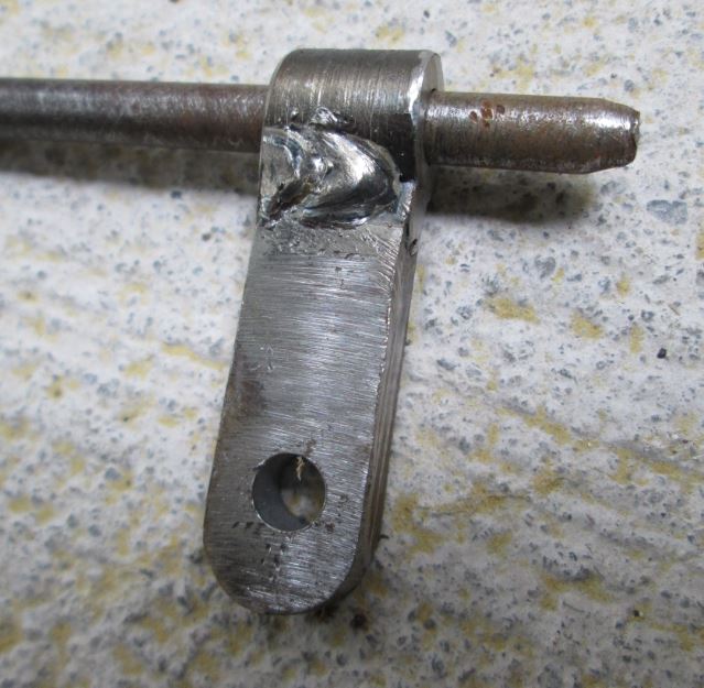
Hugh By scaling this photo, the bar thickness does appear to be 1/4", and the length to be 1 1/4". I have some small pieces of 1/4" bar which I can use to fabricate one for my car. I also have to fabricate a replacement for the radiator brace rod which screws into this elongated nut. All that remains is the eyelet which is attached to the radiator surround in the photo above. Kevin -
1925-45 where do these parts fit ?
Oregon Desert model 45 replied to Oregon Desert model 45's topic in Buick - Pre War
I will measure the cowl hood bracket and make a dimensioned drawing suitable for fabricating replacements. The U shaped bracket riveted to the firewall measured approx 1/2" wide and 3/8" deep, so I assumed the nut that fits inside (Special hex nut #47467) should be made from 1/2 x 3/8 flat bar. The length appears to be approx 1 1/4" to my eyes based on scaling the 5/16" tapped hole to the overall length. Kevin


