


Gunsmoke
-
Posts
2,598 -
Joined
-
Last visited
-
Days Won
1
Content Type
Forums
Gallery
Events
Posts posted by Gunsmoke
-
-
A friend has a NOS Shock and is trying to ascertain maker or what it might fit. Could be after market? Markings on back say P1630H, along with a A in a small triangle, the number 1, and DR (driver side?). The raised areas on front are stamped with D M X T. Other than some missing paint from shelf wear, looks NOS, no evidence it was ever mounted. Reason we figure for Ford is he mounted a couple of similar ones to his 1928 Model A touring and holes spacing was correct, and 3/4" square pivot suits model A shock arms. Unit is 3"dia, 3" high, and bolt holes are 3.5" CC. He will sell it if someone is interested.


-
Those 4 door touring bodies are a big challenge to keep everything in line, nice work. What do you have under it to keep everything straight, rigid and avoid twists?
-
 1
1
-
-
Not sure what measurements you mean, key one is center of pivot to center of 1" square hole is 8". Note from this photo that the "square hole" is actually somewhat off square on side facing rear, maybe for ease in installing locking blocks, or just a casting anomaly. It does not affect anything since wing bolt forces lock blocks to front face of opening. I understand the lower stanchion varied among models and makes (DPCD) due to shape of cowl, but many of the upper arms were common.

-
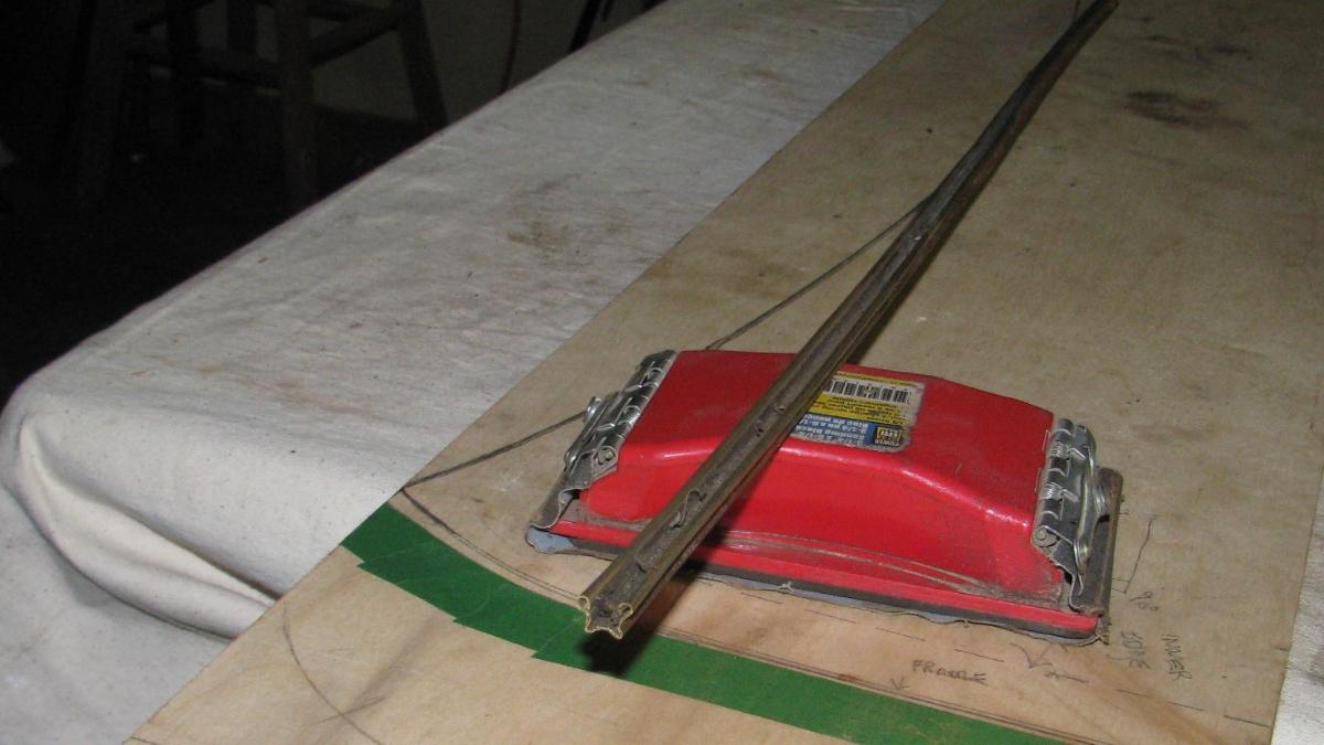
Now that top is fitted it is time to address the truncated stanchion tips. A PO 60 yrs ago cut about 1"+ off them and also flattened fore and aft a bit as well as drilling holes for wingbolts, and additional holes for home made windwings. So brazed all the key places and decided to put a bit of a dome on them as well. Then used the angle grinder with a couple of different coarse disks to get them close for a final pad sanding. These will likely be powder-coated eventually.


-
 4
4
-
-
The location of headlights seems wrong for Pierce. The bugeyes were usually centered on front of front fenders then, but OP appears to show conventional headlights, close to rad shell. Of course, an owner could have modified car to bullet headlights! Then again, there may be evidence of a pierce headlight very far out from fender, and the inner light could be a driving light installation, or a reflection of something beyond car on another vehicle.


-
Typically many convertible coupes had tie down straps to secure folded top to body ( sometimes pullman loops at back of front seat and or a strap to a rear deck cleat (see photo of 1931 Chrysler CD8 Roadster). Now just how often they were used is another question.
.jpg.b03b8824fd0d73460274be5e29ed5081.jpg)
-
1
-
-
The landau bars " snap" together when the 2 end points are fixed (WITH ONLY A SMALL AMOUNT OF "GIVE"", and the distance end points is slightly shorter than the landau bars. This is possible for example on WP's photos because in these types of convertible tops the upper pivot point is solidly connected to a wood door post piece that cannot move much. Remember many landau bars are connected to a bow that is only anchored in place by a mix of side irons and canvas top, leaving lots of play. It is those types of tops that rely on fabric tautness to keep everything together, they may need landau bars that fold in other direction (upwards), or need a hidden perhaps spring loaded locking mechanism. No simple answer to the overall question "which way is correct".
-
Great photo of the Packard 633 3/4 C/Coupe WP, is it a pre-production pic, note hood paint does not seem to match rest of car? Note it's a 2/4 passenger, some 2's may have folded tops a bit different than 2/4's related to the space behind front seats.
-
Hi Jeff: Assuming rearmost main bow is correct, easiest method is to remove other bows and set rear bow down where it normally rests and fold the side iron hardware so that it rests naturally, longish bars should generally be parallel when folded, and the various connections relaxed, not under strain, straight up and down and so on. (Bars typically are spaced apart 1/8"-1/2" or so when folded). With everything held in a firm place (temporarily brace if necessary) then carefully measure across to each respective bow mounting spots and that will tell you a very close bow dimension. Hopefully some of them will be correct! As you know, I had no bows for my Chrysler CD8 roadster. The, rear bow was an easy one to determine because it secures to fixed pivot on body (with 1/2" spacer) and sides of bow are vertical when up, so inside of bow was 53.5". Intermediate bow measured 52", and finally front bow finished at 49". They fold and stack properly. One risk of getting dimensions over inline connections is as you mention warping over time, uncertainty if bows are original, measuring mistakes (inside/ outside/ taper on bows etc). Most likely front bow is 3-4" narrower than rears and intermediate bows may also gradually reduce in width. Since it will likely have to be altered, I would plan to use a stainless steel sleeve (matching closely XxX profile of bows) about 12" long, cut front bow in half, and gradually remove some wood from ends of each cut piece, trim to slide tightly into sleeve, and slip into sleeve and check for folding freedom and do several times until a comfortable and working dimension is reached. Then either a new bow of correct dimension can be made, or the sleeved one used, by securing sleeve to bow properly. Holes/slots can be drilled in sleeve where top material needs to be stapled. Many of these tops had bows covered with cloth material anyway.
-
1
-
-
I'm with Walt 100% on this issue (and similar style issues), we need to be cautious about assuming everyone did things the same way, or even that one manufacturer always did it one way, or the factory guys always got it right. To prove the point, here are 2 1929 Packard convertible coupes similar to those I posted yesterday, with their folded landaus. I'm not prepared to tell either owner that theirs are right or wrong. For the ones that fold rearward, remember the top material typically went back several inches, and canvas boot would have covered everything and left side of car clear. While I prefer look of those that fold forward when they are folded, my engineering mind suggest gravity should require the knuckle to be on bottom when they are opened. Is there a lesson here? Yes, don't assume anything, because we all know that word can make an ASS out of U and ME.


-
So here are a pair of 1929 Packard Convertible Coupes, who is the authority on which set of landau bars is correct, or are both correct, one is a model 633, other an 8cyl. I'm guessing there are to many possibilities over the years on how these were from the factory and how restorers decided they should look.


-
WP said "Apparently the double landau bar cape tops work differently, and the top is intended to sit way out back when in the down position. So, 3Makes' first diagram is correct.... AND I stand corrected". It was actually my first sketch, but 3Makes can have credit as he inspired my second look. I'm guessing with proper locking mechanism (to avoid gravity issue) 4 piece bars could fold either way. WP is this the first time ever you "stand corrected"? I'm guessing the Mercedes alsuncle posted has some form of locking mechanism to prevent gravity from taking over.
-
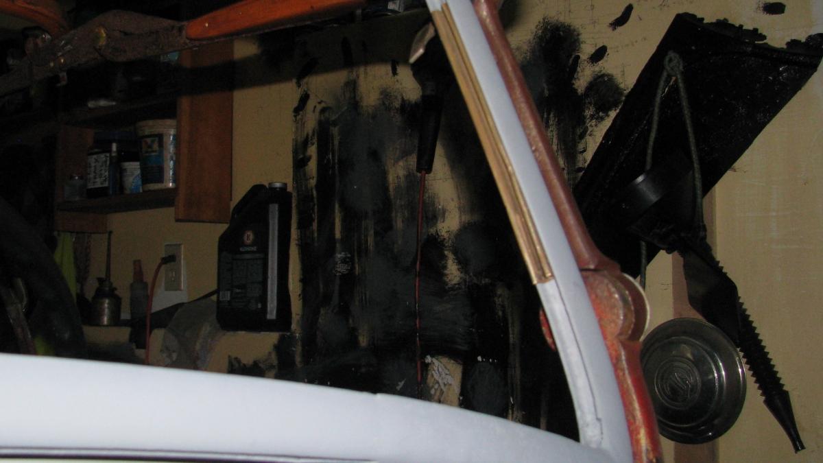
After fitting the socket clamps for the top, time to make the soffit for front bow. Bought a piece of 18 ga stainless steel 4.25x48 and had shop break one edge 5/16" with rounded corner. After carefully locating all the screw connectors to top clamps and drilling out the 7/8" stanchion holes (means putting it together and apart 7 or 8 times!), I secured it in place and marked for trimming to suit bows. Then drilled and countersunk 6 holes for stainless screws into bow. For now I drilled and rasped a slot for each 3/8" clamping bolt. I set soffit so inside edge abuts the top clamp bracket to side of bow, did not want to take it any further into cabin than necessary. The soffit seems plenty stiff and should need no further material. It hides most of the top clamp when sitting in car. Might eventually be a convenient spot for storing a cell phone, papers, etc (no glove box) so may eventually line with felt or something quiet. Area around bolt may need tweaking depending on upholster's thoughts, but I see him making a 1/2" pocket to go around bolt.


-
4
-
-
hmm... 3makes, I'm not sure I have it right above. Here is a second sketch based on Landau bars folding forward as top is lowered. This seems correct. However landau bars on subject vehicle would need to be reconfigured to allow this folding method, left/right, upside down, backwards, I'm not sure just what is required, but I now agree that WP (and Walt) identified them as not right. Mea Culpa.

-
The car in question has a 4 piece landau bar setup, and I suspect folds like this sketch. Lowering top means first folding rear landau bar rearward as shown, which would fold the bar and drop main bow to resting spot. Then the second landau bar would be folded rearward so remainder of roof and forward bow lies flat. Note the requirement to have equal distances from forward body top mounting pivot point to the 3 places landau bars are fastened to rear bracket or to bows. As to the question raised about landau bars being possibly wrong sided, I'm still not sure that there is any way for them to work other than as installed. My understanding bars are always installed so gravity and some compression keeps them locked in place. I suppose there is also a way to have rear bar fold forward first and also have second bar fold forward? Update, having now looked at the implications of the landau bars sticking out back of car, I figure bars must fold forward, and that bars as installed are likely wrong, Not sure left/right changes is issue, perhaps they need to be reassembled to fold forward.

-
3
-
-
WP and a couple posted a couple of pages back "Better photo to see that the landau bars are mounted upside down (need to swap sides)." Not sure they are, cannot imagine a show of this caliber a submission making such a booboo. They are complicated folding mechanisms for a complex top, so I think may be correct, even if they do look strange. But what do I know.
-
Ingenious option, I will consider it. Sliding glass into a 3 sided stiff frame with tape on sides is likely a tricky thing to do, perhaps some soapy water would help. That was one of the advantages of the brass insert, once on the glass it would slide into frame easily. I looked at several restored CD8's no evidence of an insert on any of those, but may have been lost during restoration. Won't be installing glass for a few months likely, so lots of time to reflect on best approach. I may get a small piece of safety glass from the shop and experiment with some solutions like you suggest. The lower corner curves will be a challenge, little wonder shops just use silicone.
-
Any suitable solution that eliminates plastics wherever possible is best for everyone.
-
2
-
-
The frame groove is under 3/8" wide, and safety glass is just under 1/4" so about 1/8" space to make up. The auto glass shop guy suggests using what he called glazing felt, a long used product from years ago often used for setting glass in quarter windows and doors, etc. It is some sort of felt type product with a waterproofing of some sort, about 1.5" wide in a roll. He would wrap edges of glass (might need 2 or 3 layers, I note the insert I have has 2 layers of cloth) and tape the product in place temporarily while he sets glass snugly into frame. Once together, excess would be trimmed off. He is not aware of anyone selling a rubber U channel for safety glass (or any other suitable channel), but indicated someone may make such a product. I'm not ready to install glass yet, plan to have frame powder-coated beforehand. I know the Filling Station in Oregon sells a variety of rubber channels as do Steele rubber Products, I checked Steele catalog, nothing suitable.
-
Unfortunately I only have a couple of scraps of the brass insert, not something that any one is reproducing I suspect. I pulled out a small scrap of the "tape" and it is about consistency of friction tape and a similar fine cloth. Their system was quite ingenious. Assuming they fit tape to glass and then brass/nickel insert over tape and then slipped assembly into frame, any slight fit issues could be fixed by just tapping nickel strip tight to frame. While I didn't see any evidence of an adhesive on insert, after 90 years who knows if there was some? The frames I started with were painted black originally, some later cars had chromed frames. I have not noticed this "insert" on any CD8 frames so will have to do some more serious looking. Think they may have been set in a rubber U seal.
-
I figure the glass was fitted with a stick on cloth tape (about consistency of cloth friction tape( wrapped along each edge about 1/4", and the glass with taped edges slipped into the brass insert, which btw had 90 degree overlapping bends at corners. (I haven't figured out the brass insert was curved for lower rail? The edged glass (with tape and brass trim) was then slipped into lower rail and side pieces. Then the top rail would be installed. The glass unit would be a tad undersized for frame, but the beads on the brass insert would prevent glass from going too deep into groove and tapped fully into groove to keep glass fitting neatly. In any event, a visit to the glazers this week may reveal what is available to accomplish a neat similar "dry fit". The groove in the frame is a tight 3/8" wide, and about 5/16" deep.
-
2
-
-
Frank wrote "Yes, but the original poster was buying oil for their daily driver, which is built since 2000." That outlines one of the problem posting non-antique car questions on AACA. Eventually the topic drifts into application to antique cars (as per several of above replies), and the discussion shifts to antique cars generally, which is why I posted about the study. Prior to my comment I think one response implied synthetic was fine for all engines. From what I've read, not sure that is true.
-
A bit of a look back, but you can imagine my excitement back in 2017 when rummaging thru a then 99 year old's parts horde in the attic of his barn, I dug out this windshield. Man did it look like what I needed. When I got it home I realized it was about 3" too narrow (about 39", I needed 42"), but sides fitted against stanchions perfectly. Unfortunately the lower 2 corners were rusted thru, and the curve of lower rail was too severe for the CD8. The old gent also had a couple of other partial Chrysler/Dodge frames, some solid, some straight, some curved. Told me I could have them all free. This was the first time I also saw the unique mounting pivots, even had one piece of the locking blocks, the special locking washer shown etc. These eventually enabled me to make the finished product. Of note, these windshields (see pic of old one) used a U shaped brass insert, cloth (linen) lined, that set in the frame and held the glass, leaving a nice neat small bead visible both sides. I have a few pieces taken from the older windshield and am wondering if CD8's used it, and if anyone makes this product. Plan to take windshield to local glass shop this week and see what they recommend for a "dry installation", would prefer not to set glass in silicone. All in the details eh!


-
1
-
-
hmmm thinking perhaps earlier radio box? Anything tell-tale inside?
-
2
-


.jpg.b03b8824fd0d73460274be5e29ed5081.jpg)


Late 20's Touring Car Top, what Make?
in What is it?
Posted
A friend has this touring car top, wondering what it may have fitted. Bought it several years ago, was told it was late 20's GM. As shown has 4 steam bent bows all set into steel socket style arms, front 2 bows measure about 56" wide out to out, and rear 2 bows measure about 57" wide out to out. Front header clamps are stamped 725-505. front and back bows are flat along length, while other 2 bows have about 1" of curvature over length. Bows are solid except front bow which is cracked at one end. He's asking $200 for it. Any ideas of what it might have been on?