


Taylormade
-
Posts
2,396 -
Joined
-
Last visited
-
Days Won
1
Content Type
Forums
Gallery
Events
Posts posted by Taylormade
-
-
Well, another fly in the ointment. My front U-joint was a greasy mess, so I decided to take a look inside to make sure everything was in decent shape. Lucky I did as the joint was worn out to the point that the bearings were turning in the housing. I think the shafts of the joint were so worn they became eccentric and started the bearings rotating. Anyway, it was a real mess and destined for an early and probably catastrophic failure in the near future. Luckily, I had a spare U-joint that came with my extra transmission. I took that one apart, too, just to make sure and everything seems to be in good shape.
Now, and with no little worry, I have to take the rear joint apart and examine it. I assumed it was fine, but after the experience with the front joint I'm no longer sure of anything. Bottom line, I'm glad I dug into all parts of this car during the restoration as I have found bad seals, bearings, gaskets, gears and assorted other problems lurking under what appeared to be a solid car mechanically.
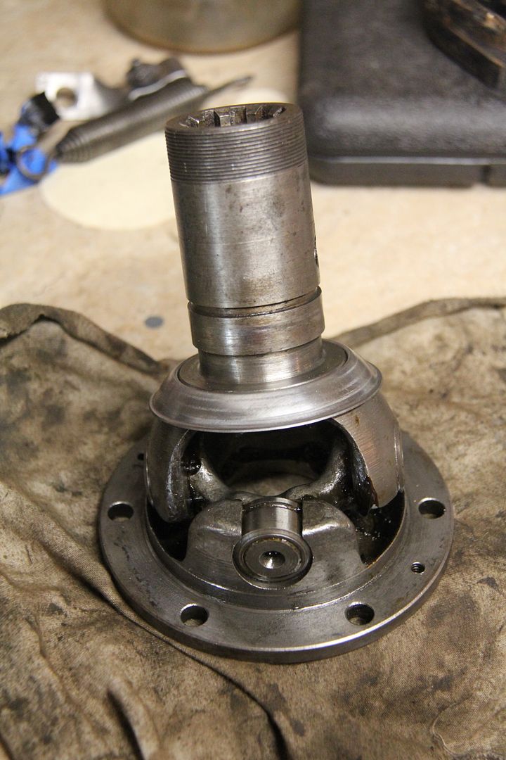
I do have one question - a problem I need to solve. A part of the U-joint that rotates over a metal housing has a cork seal around its outer edge. You can see it in the following photo. It's black with grease, but it is cork and not rubber.
As you can see, it's in rough shape, with a piece missing. It fits into a groove on the part. Any ideas how to fix/replace the seal? I might be able to cut a thin strip of cork from a sheet and get it into the grove. Another thought was to use an O-ring of the correct size, but I'm not sure if the rubber would allow smooth rotation on the opposing part. I'm more than open to any ideas.
-
Yes, that really helps. My manual is a bit harder to see. This is the way I put mine in, so I guess I'm good to go! Thanks!
-
My thinking exactly. Since the body is off and I have no floorboards for reference, perhaps I'm pushing the pedal too far forward and that is why the arms are going all the way to the disk. I can push the pedal in about two inches and it realeases the disk and I can spin the pinion shaft, so maybe I'm okay.
-
Remember those famous last words? I think I may have the clutch disk in backwards. When I depress the clutch pedal it looks like the clutch plate arms are making contct with the disk. On one side of the disk the center section projected outward about 3/8 of an inch. The other side was flat. I assumed the projecting side would not clear the bolts on the flywheel and that it should face toward the rear. I think I was wrong. Anyone have any ideas on this before I take everything back apart?
-
Got the transmission in today. If I had it to do over again I would have put the trans on before I dropped the motor in. Live and learn.
This is the oldest trick in the book, but it sure helps getting the tranny in place with less effort than normal. I just cut the ends off two long bolts and replaced the bellhousing studs with them. You just slide the transmission along the bolts/shafts.
Since my wife and I put the trans in together, there was no one around to take any photos, but here it is in place. The rubber mount makes it difficult to get the frame member that is attached to the trans by the rubber mount into the space in the X-frame. I had to put the motor back on the lift and pull it up a bit so I could wrestle everything in place. It's a real bear of a job, but it's finally done and I'm hoping I'll never have to take it out again in my lifetime. Famous last words!
-
I'm not posting this as criticism but as more of a desire for folks opinions. From all I can determine, Dodges of this era used bolts that were stamped with a DB logo on the head. My DL had most of its original bolts, and wherever possible, I cleaned them up and reused them. This begs the question - are eighty year old bolts safe to use in areas like motor mounts and other high stress situations? Grade eight bolts would probably be better, although most of them are undoubtedly made in China, so who knows what you're really getting? Also, the rest of the steel on the car is eighty years old, so should I replace that, too?

Those brackets look great, but the Phillip head screws and the modern marks on the bolt heads bother me. Call me compulsive, but I ground off the modern markings on my replacement bolts and found the correct slotted screws used during my cars era. A stupid waste of time?
-
On the 32s, they used both a long and a short tail light stand. My eary car has a long stand, while my buddy Phil's later car uses a short stand. Why they changed...who knows?
-
Very nice, and a bit more streamlined than the 32 DL.
-
Bummer! Is it the cylinders that are frozen up?
-
Thanks, just what I need.
-
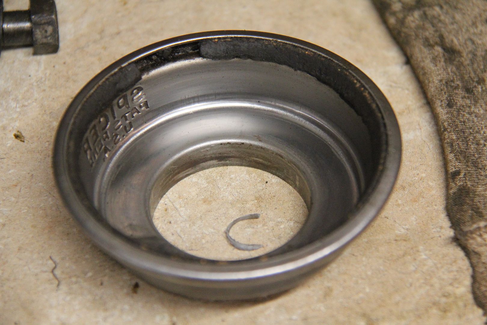
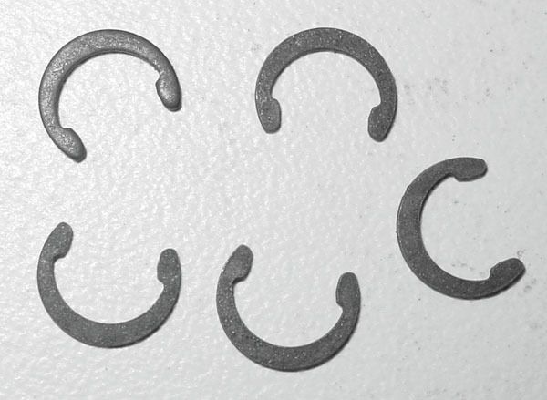
I'm looking for this type of C-clip for a .75 (3/4 inch) shaft with a .625 (5/8 inch) groove. I can't find anything in the Restoration Specialties catalog, but I may have missed them.
-
I'm looking for this type of C-clip for a .75 (3/4 inch) shaft with a .625 (5/8 inch) groove. I can't find anything in the Restoration Specialties catalog, but I may have missed them.
-
I'm looking for this type of C-clip for a .75 (3/4 inch) shaft with a .625 (5/8 inch) groove. I can't find anything in the Restoration Specialties catalog, but I may have missed them.
-
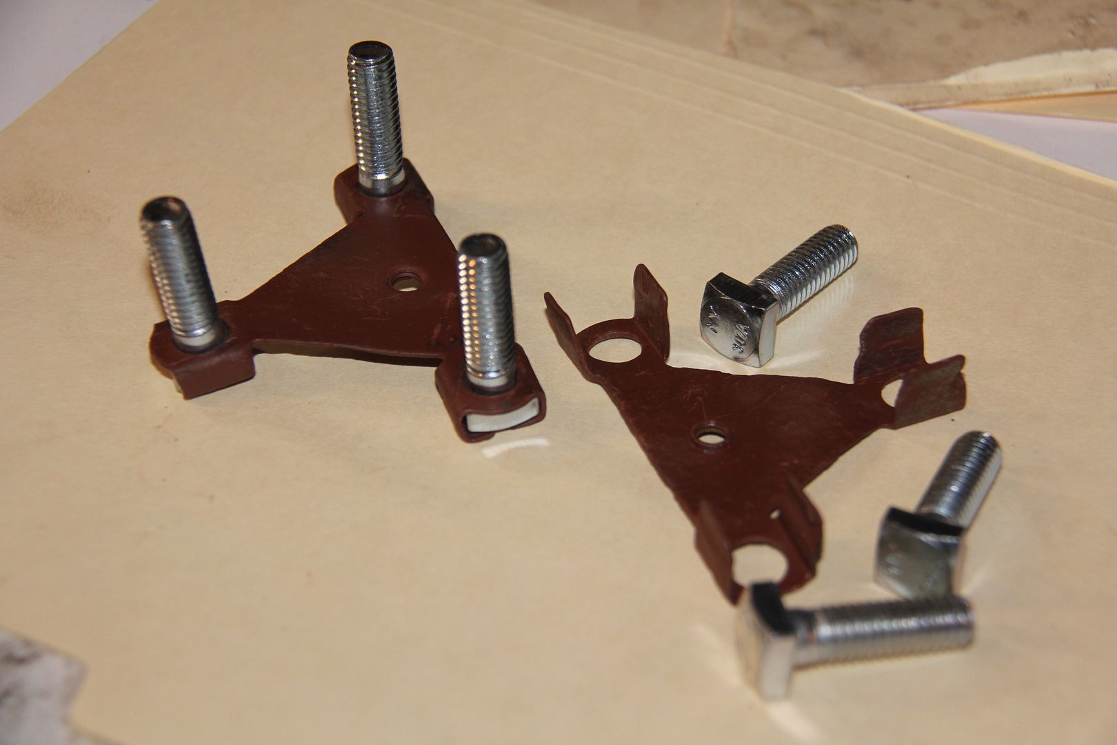
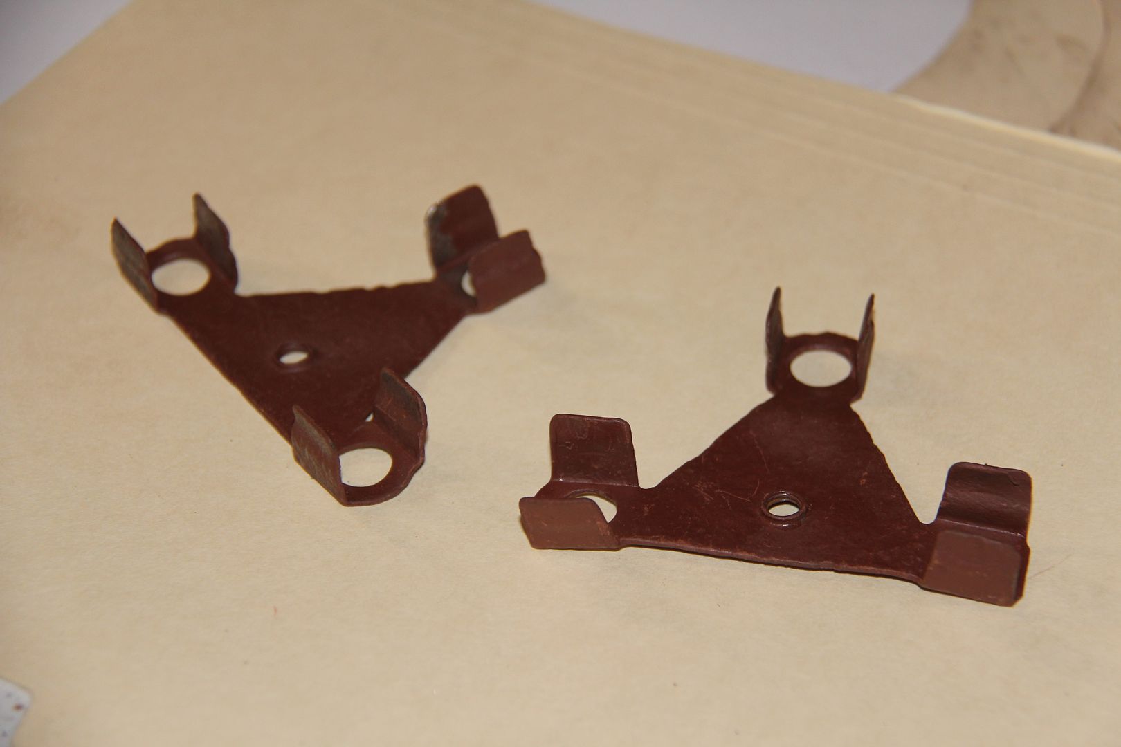
Ron takes the prize - front fender support bolts.
-
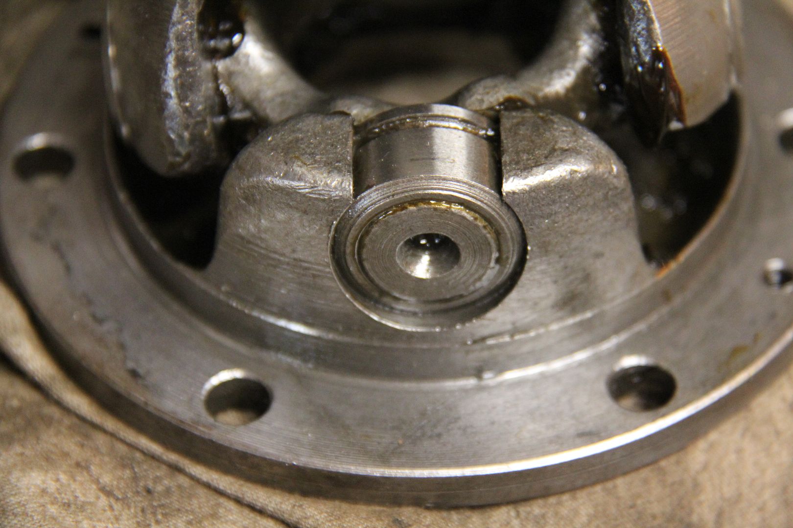
Correct. Do you know what they are used for? And what is the purpose of the hole in the middle? (By the way, finding the correct sized square head bolts was not easy.)
-
It's her sweet revenge.
Daphne - "Didn't want to change my transmission oil back in 1965, Dick? Have fun changing all my transmission bearings now."
Dick - "Yes, Daphne."
Daphne - "Ever going to treat me like that again?"
Dick - "No, Daphne."
-
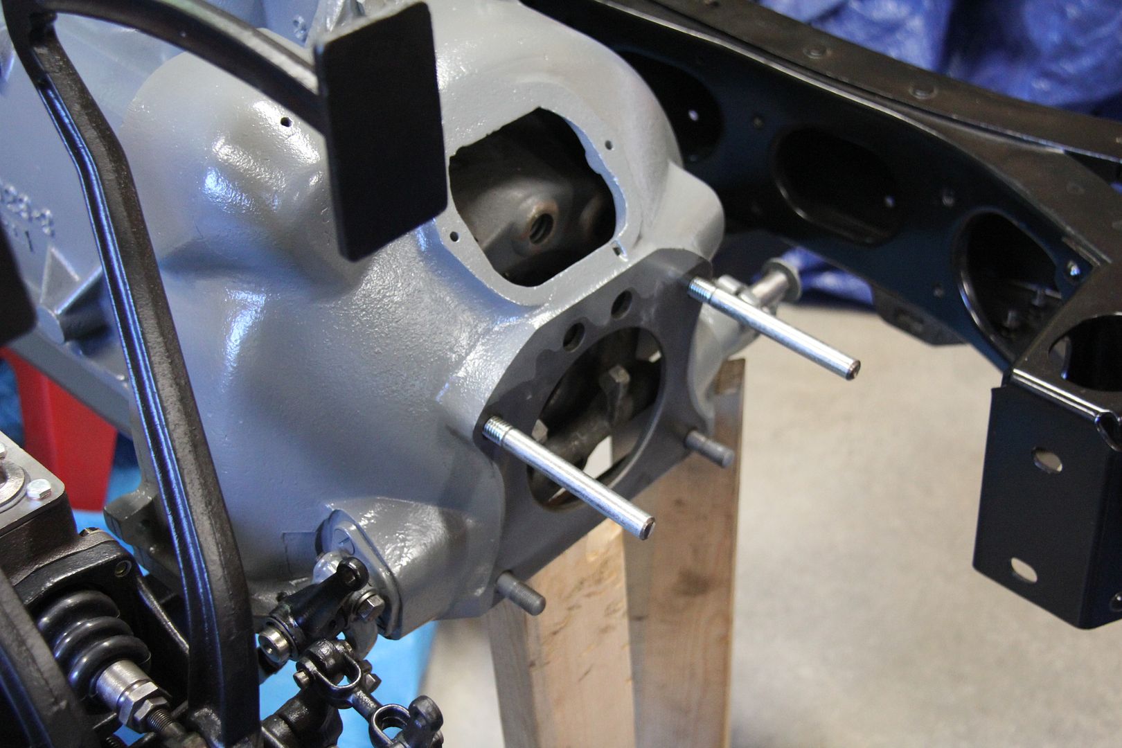
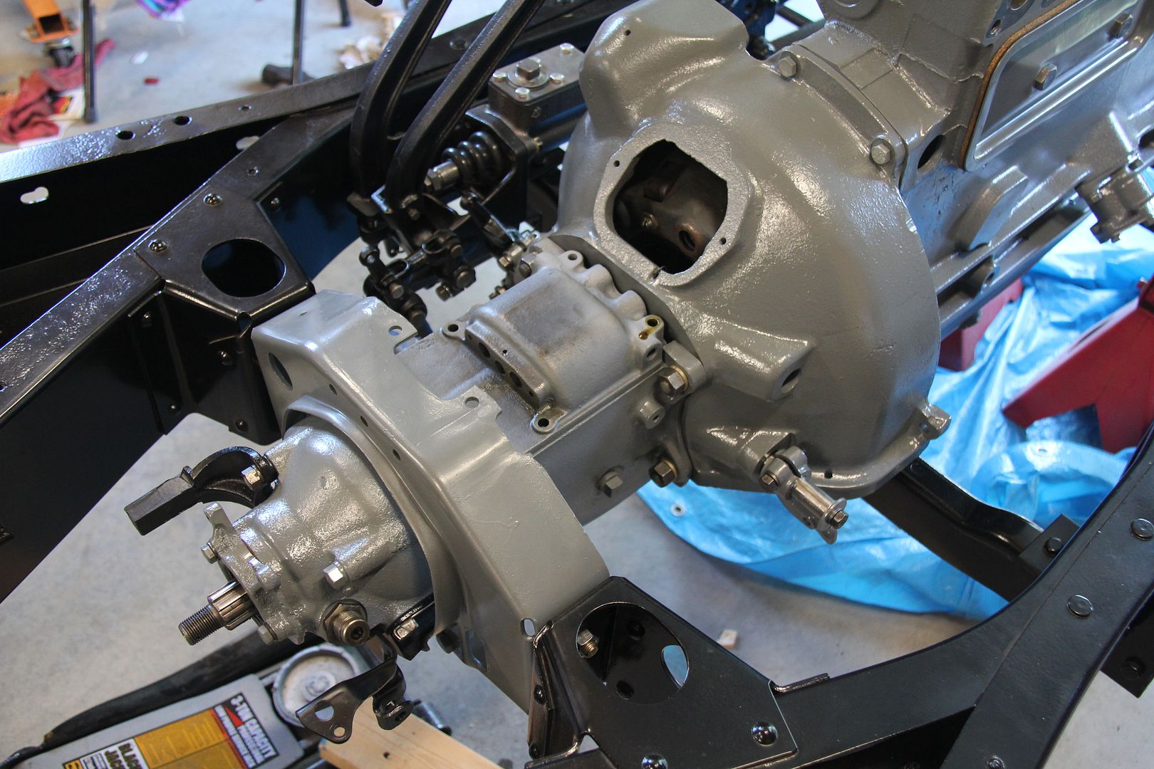
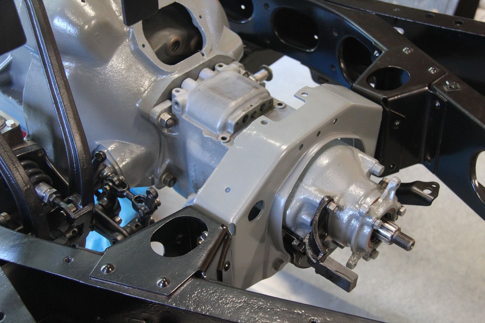
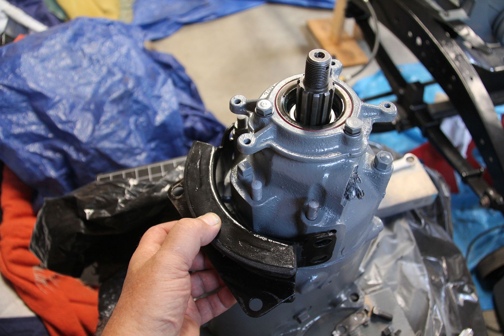
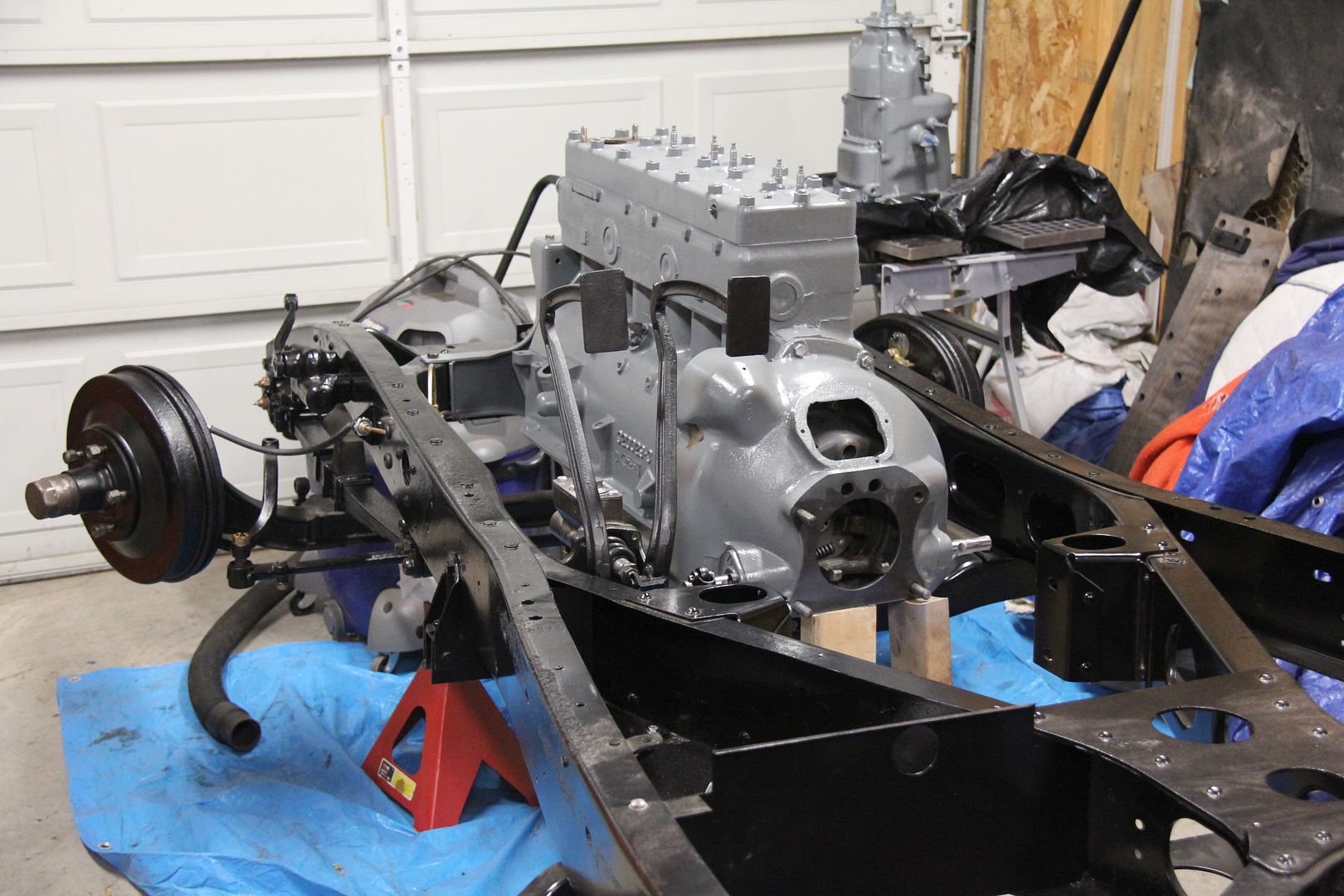
Just went through one of the biggest pain in the you know what jobs in the restoration so far - installing the transmission rubber Floating Power mount. Sometimes I wonder how they did some of this stuff at the factory. It looked simple, bolt on the rubber mount, slide the frame member on and bolt that to the mount.
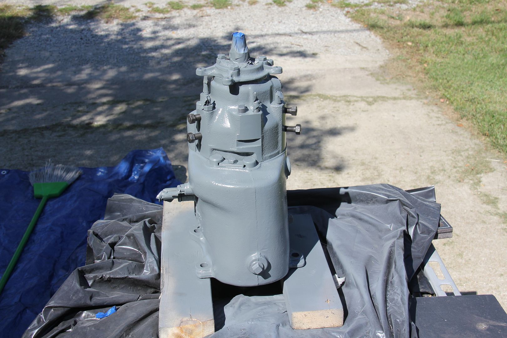
Here is where the rubber mount goes on the back of the tranny.
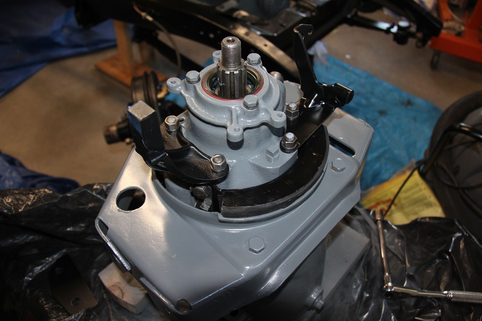
Two bolts on each side. Simple - right? Then I go to slide the frame member on and it won't fit! Ahhhh, now I see - I have to bolt the rubber mount to the frame member first, then slide everything over onto the transmission. So i unbolt the mount from the tranny, bolt it to the frame member and...now there is no room to get the four mounting bolts in. Unbolt everything, stare at the parts for a few minutes, bolt the rubber mount back on the transmission and twist, slide, force, beat, swear, turn and finally get the frame member over the bolts on the transmission and down on the rubber mount. Naturally, my freshly painted transmission looks like I dragged it behind a truck with a chain.
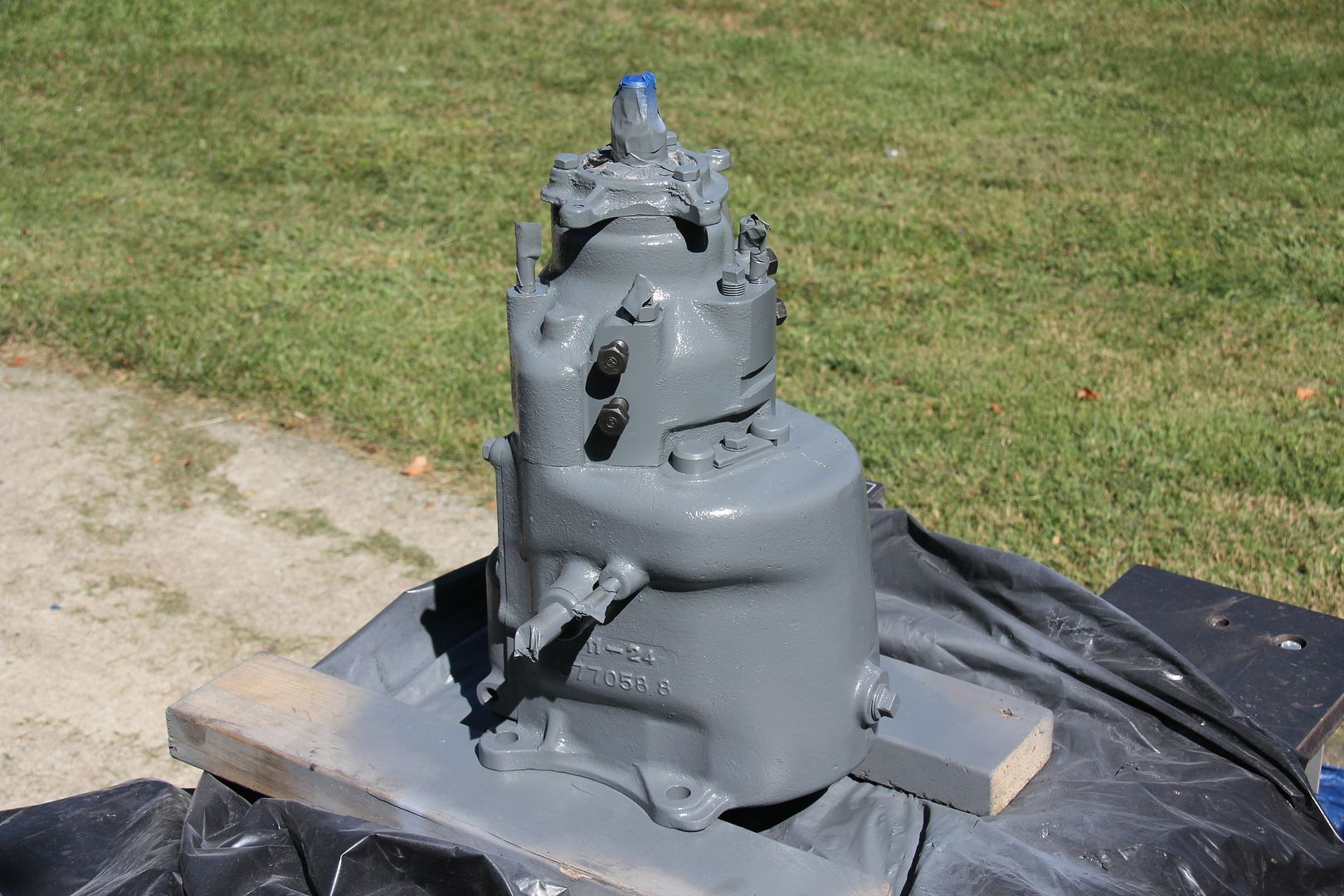
Here is the transmission, freshly touched up, with the rubber mount and frame member in place. Oh, and getting the two bolts that hold the rubber mount to the frame member is almost impossible as there is absolutely no room to get your hand in there and get the nuts on. They must have had to carry the guy who did this at the factory out on a stretcher at the end of his shift.
-
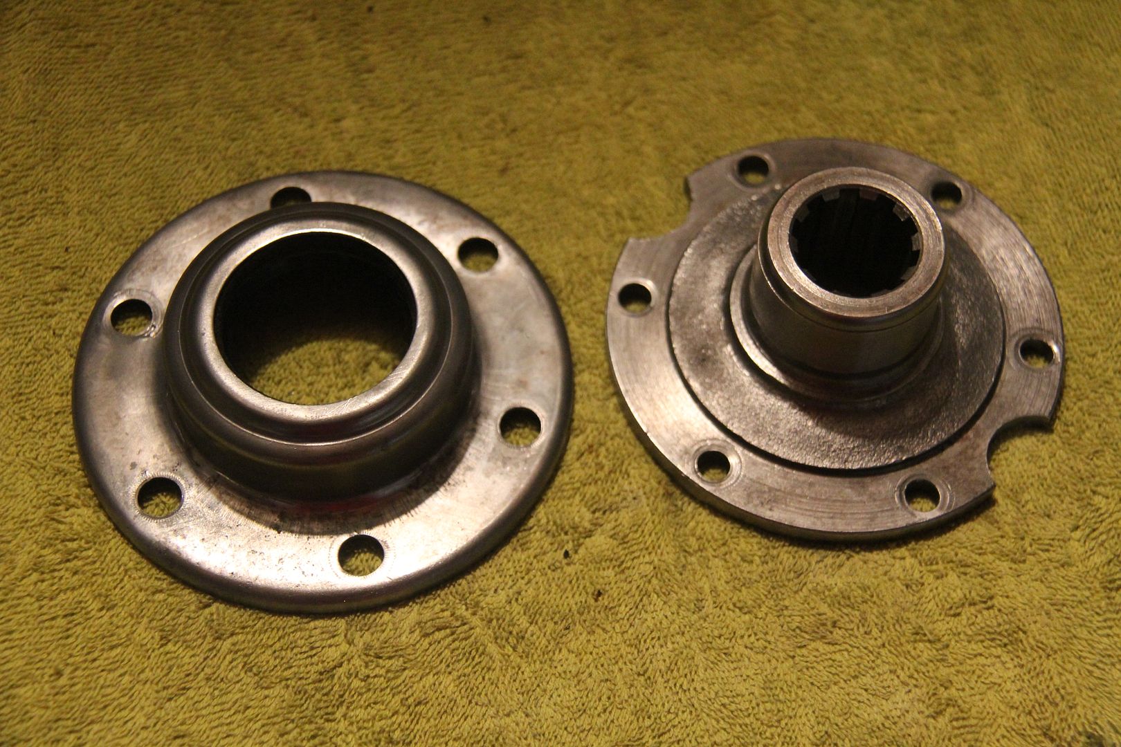
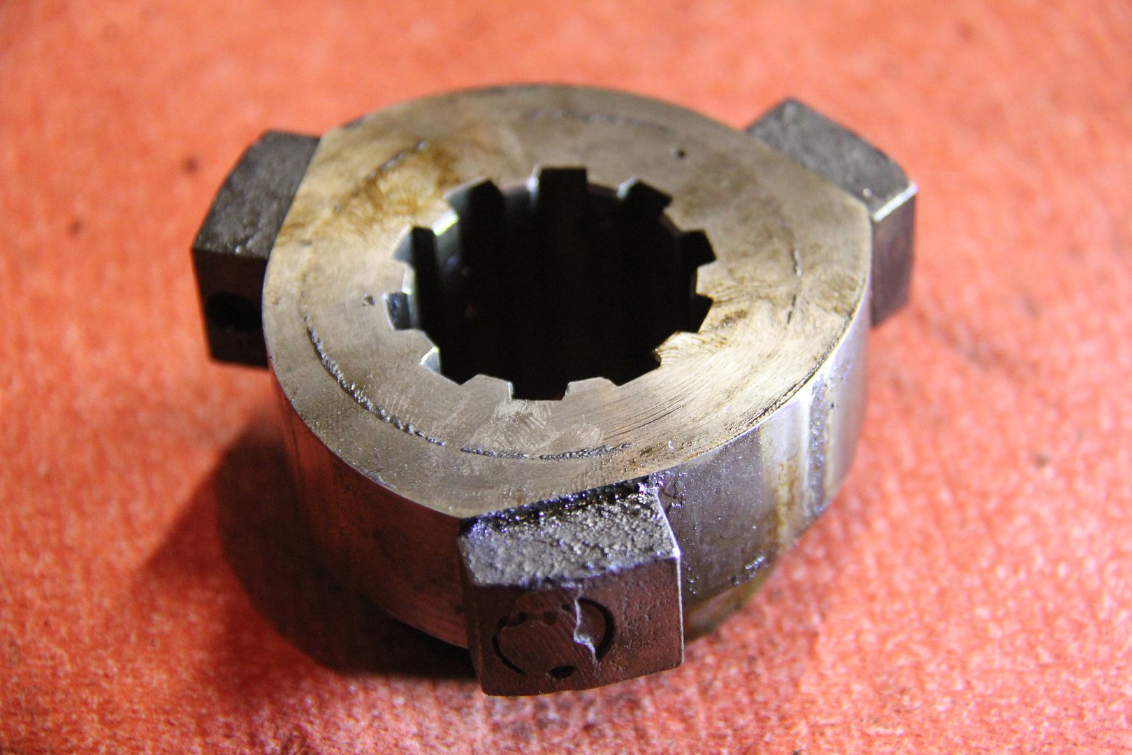
Today's Pop Quiz in Dodge Brothers 101.
What are these objects? (They are from a DL) The winner gets the satisfaction of being the smartest student on the forum.
-
After all that, I noticed it was your transmission seal, not the differential seal you were talking about. Sorry about the long winded explanation for nothing, although the Speedi-Sleeve trick will work on your front yoke, too. On my 32 Dodge, which has a free wheeling unit on the back of the transmission, I used a Timken 450494 seal. I took the rear housing to the bearing shop and they helped me find the correct size, which was 1.750 X 2.502 X 0.375. If you have the same tranny, this one will work. If not, they can help you find one.
-
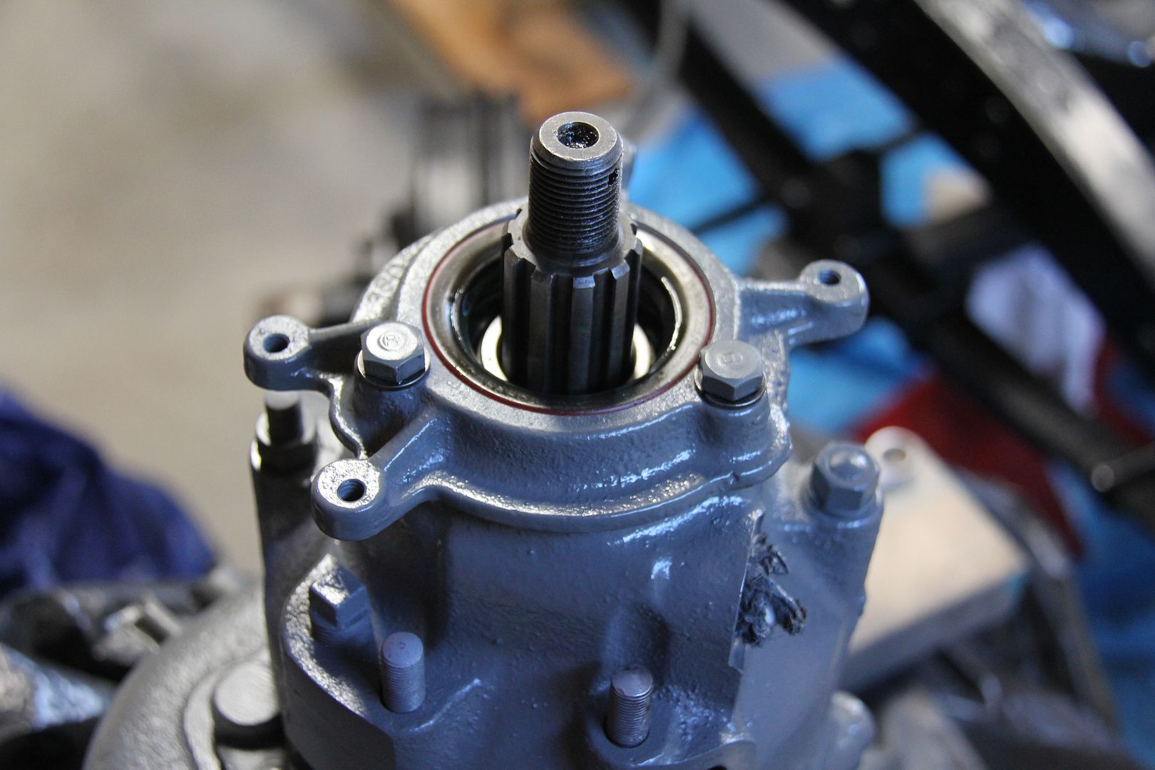
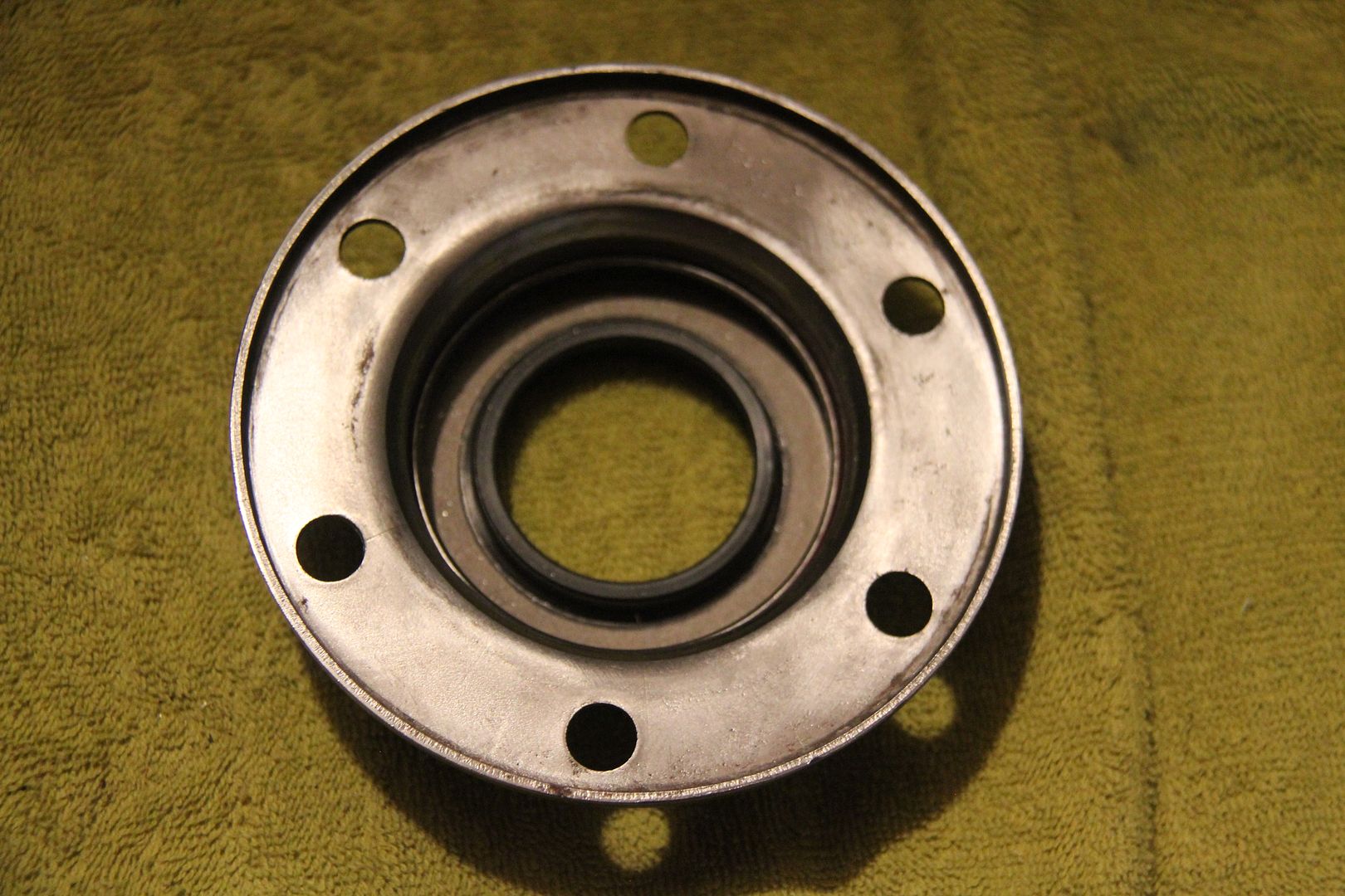
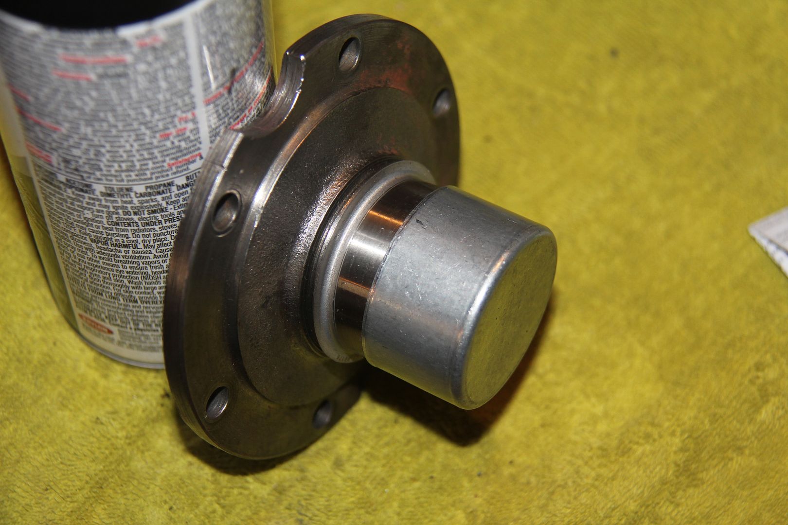
The problem - wear on the tailpiece shaft and a shot seal for the shaft.
First I tackled the seal. Early Mopars used these huge seals on the differential and the rear axles. You can find them on EBay, usually at an exorbitant price, and being new old stock, they have a tendency to be dried out or warped. The seals are rawhide and are "permanently" attached to the large metal piece that bolts in place. Well, not so permanently I discovered. After drilling through most of the top of the actual seal, being careful not to damage the housing, I managed to pry the old seal out. It was totally destroyed in the process. There was no number or any ID on the seal. The felt seal at the top center was sandwiched between the seal and the housing and was in pretty good shape. i believe it was mostly to keep dirt out of the housing and I put it back in place before installing the new seal.
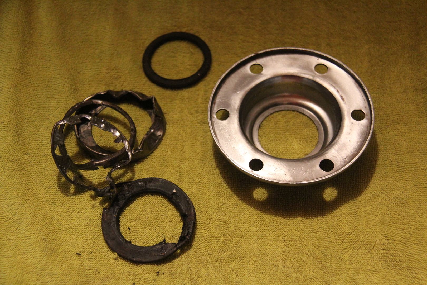
After I cleaned up the housing, I measured in inside diameter of the area where the seal used to live. It came out to 2.750 The shaft diameter of the tailpiece was 1.750. I found a Timken seal, number 473447, by going through their applications charts online. This seal measures 2.758 OD and takes a 1.750 shaft. The interference fit seemed about right so I ordered a seal from my local bearing house.
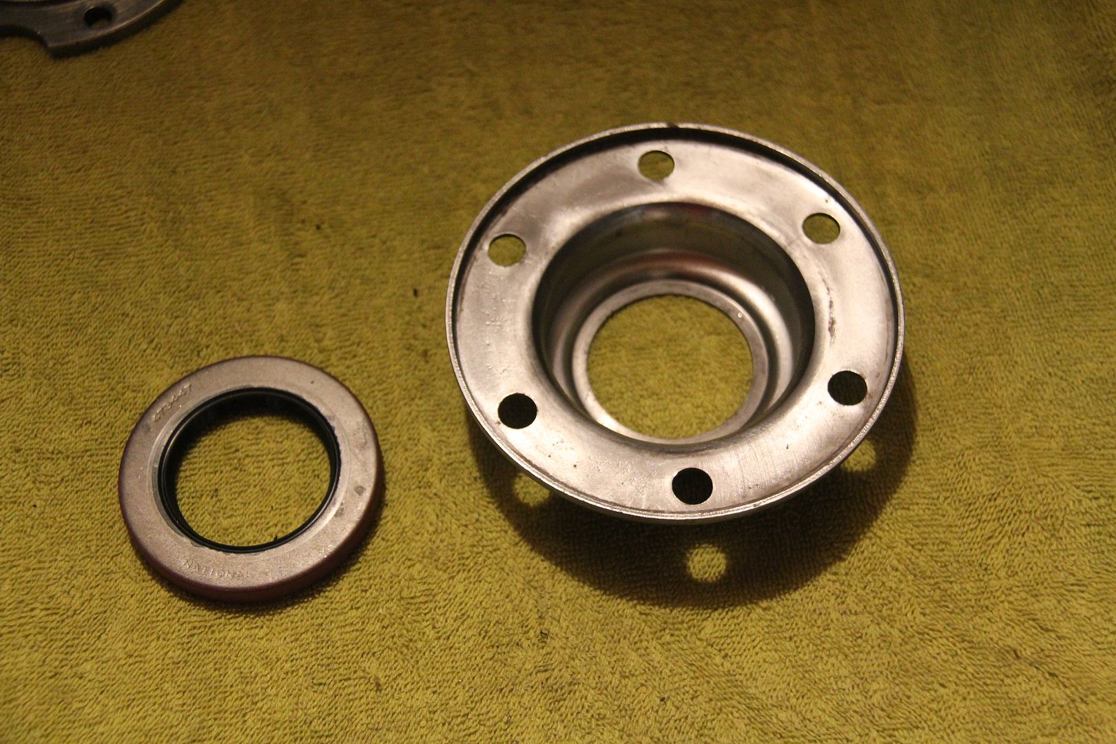
I drove it into place with my bearing race driver. It seated nicely and I was ready to work on the tailpiece.
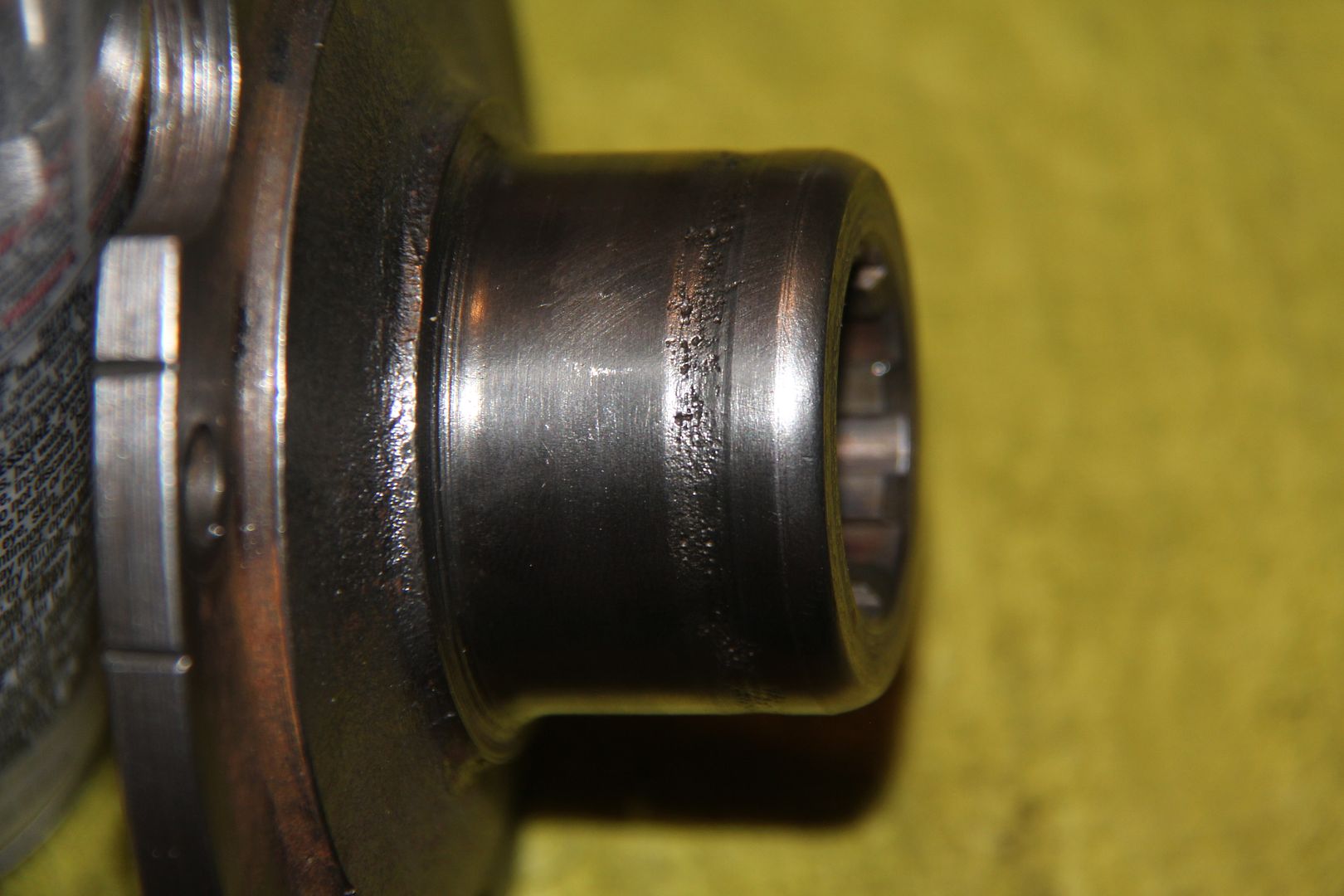
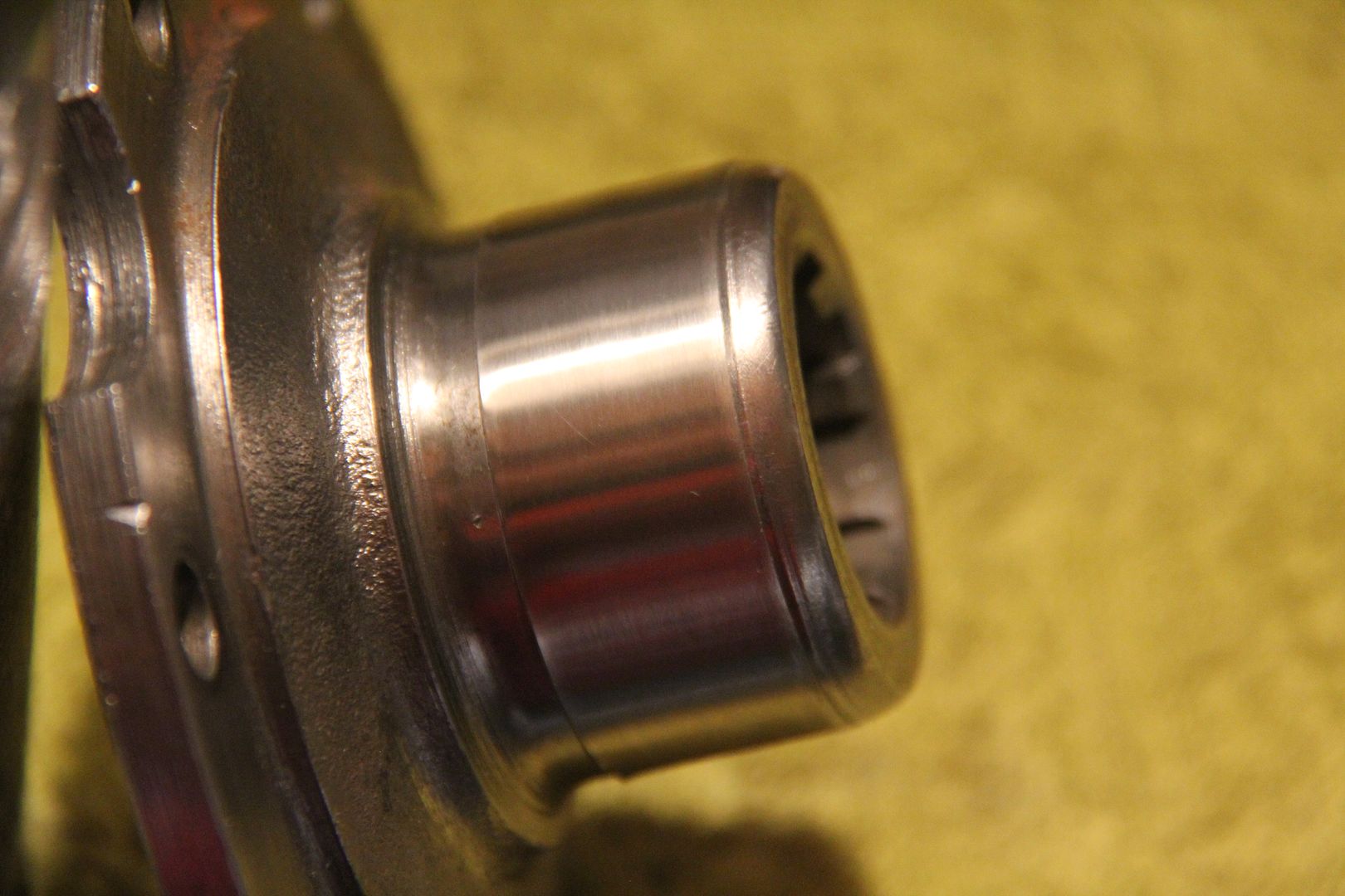
The problem here was the groove worn into the shaft by the old seal. Not a pretty sight.
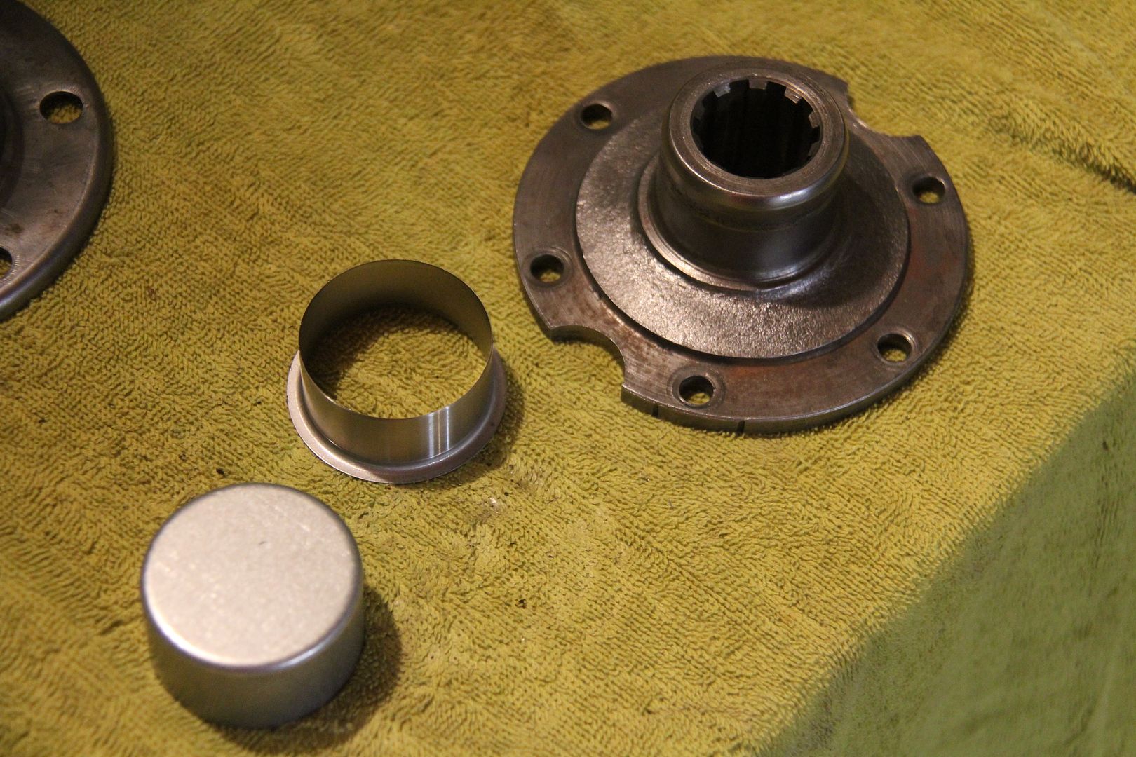
To address this situation I also bought a Speedi-Sleeve from the bearing house. This one was designed to work on a 1.750 shaft. The sleeve comes with an installation tool. The sleeve simply fits over the shaft and provides a new surface for the seal.
The groove in the shaft was deep enough that I used a small amount of epoxy filler to fill it in. Drive the sleeve on before the filler dries.
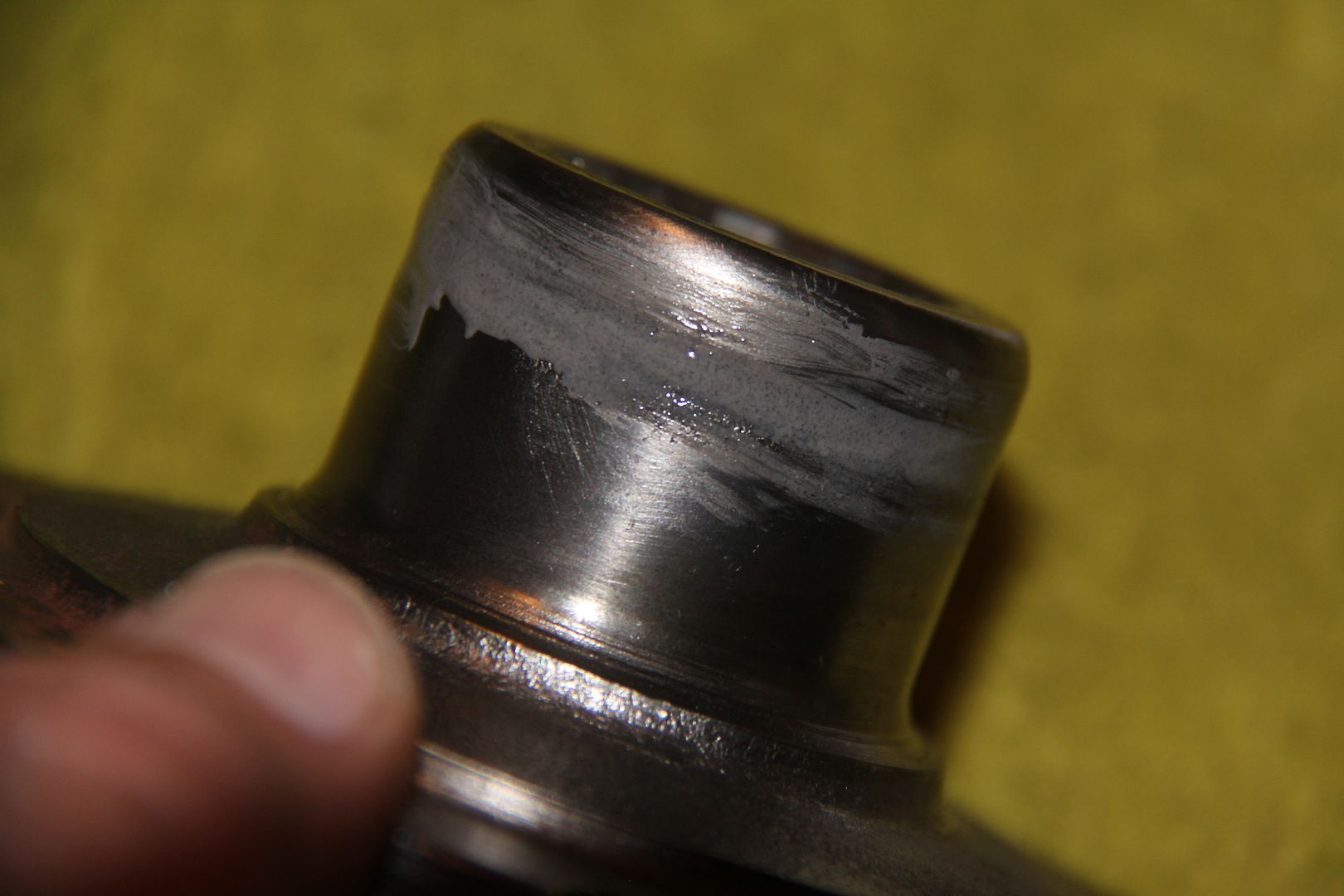
You slip the installation tool over the sleeve and drive it onto the worn shaft.
Once the sleeve was in place, I removed the lip used by the installation tool to drive it home as it wasn't all the way down on the shaft. If the sleeve is long enough and seats, you can leave the lip in place..
Parts finished and ready for paint.
I hope this helps.
-
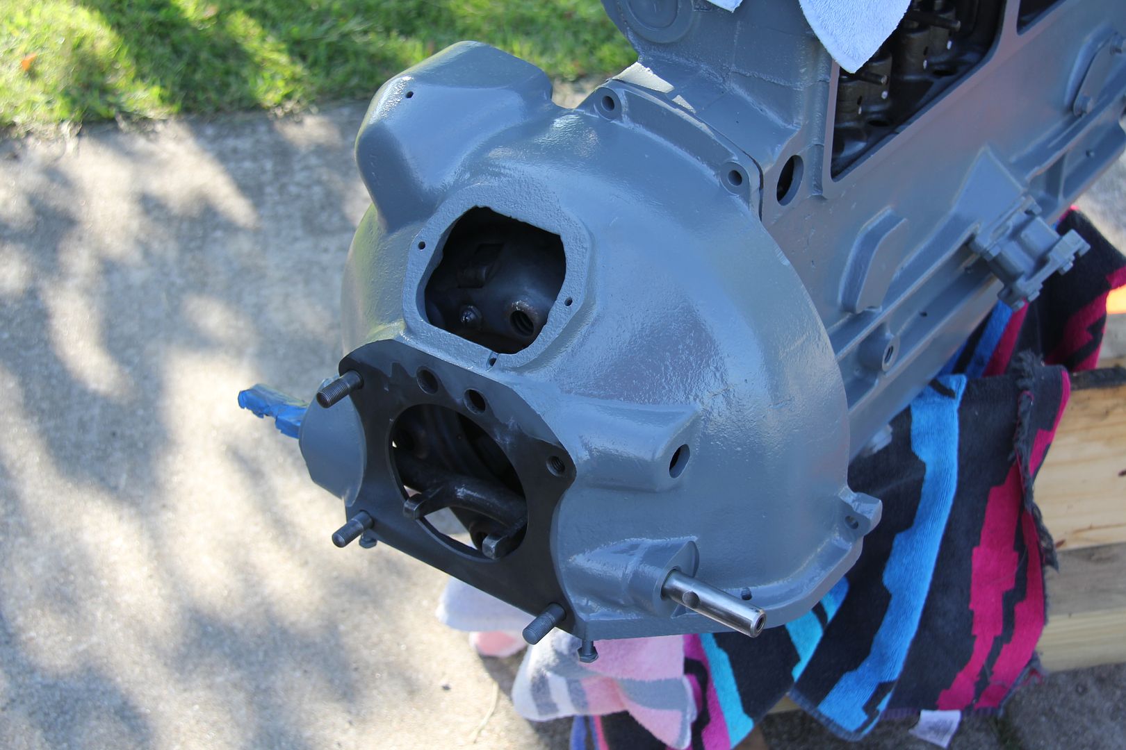
Floating Power is an unusual system. If you notice, there are no conventional "ears" connecting the bell housing to the frame. There is a rubber bumper or pad on the cross frame right behind the oil pan, but the motor is not attached to the pad. The pad is just really a cushion for the motor. Then the transmission rests at the back on a rubber mount, so the engine and transmission float on two rubber mounts at the front of the motor and the rear of the transmission. They never touch the frame.
-
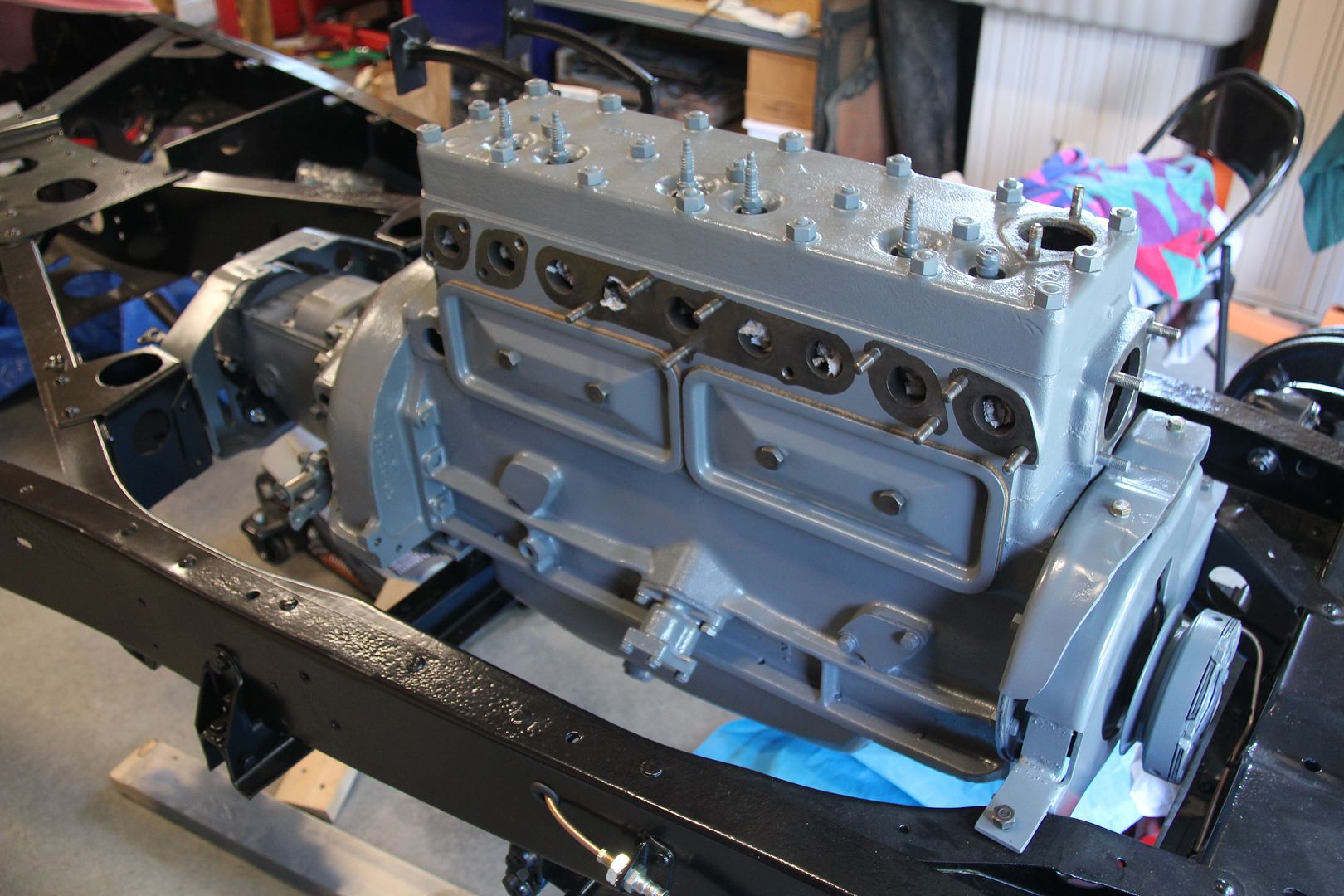
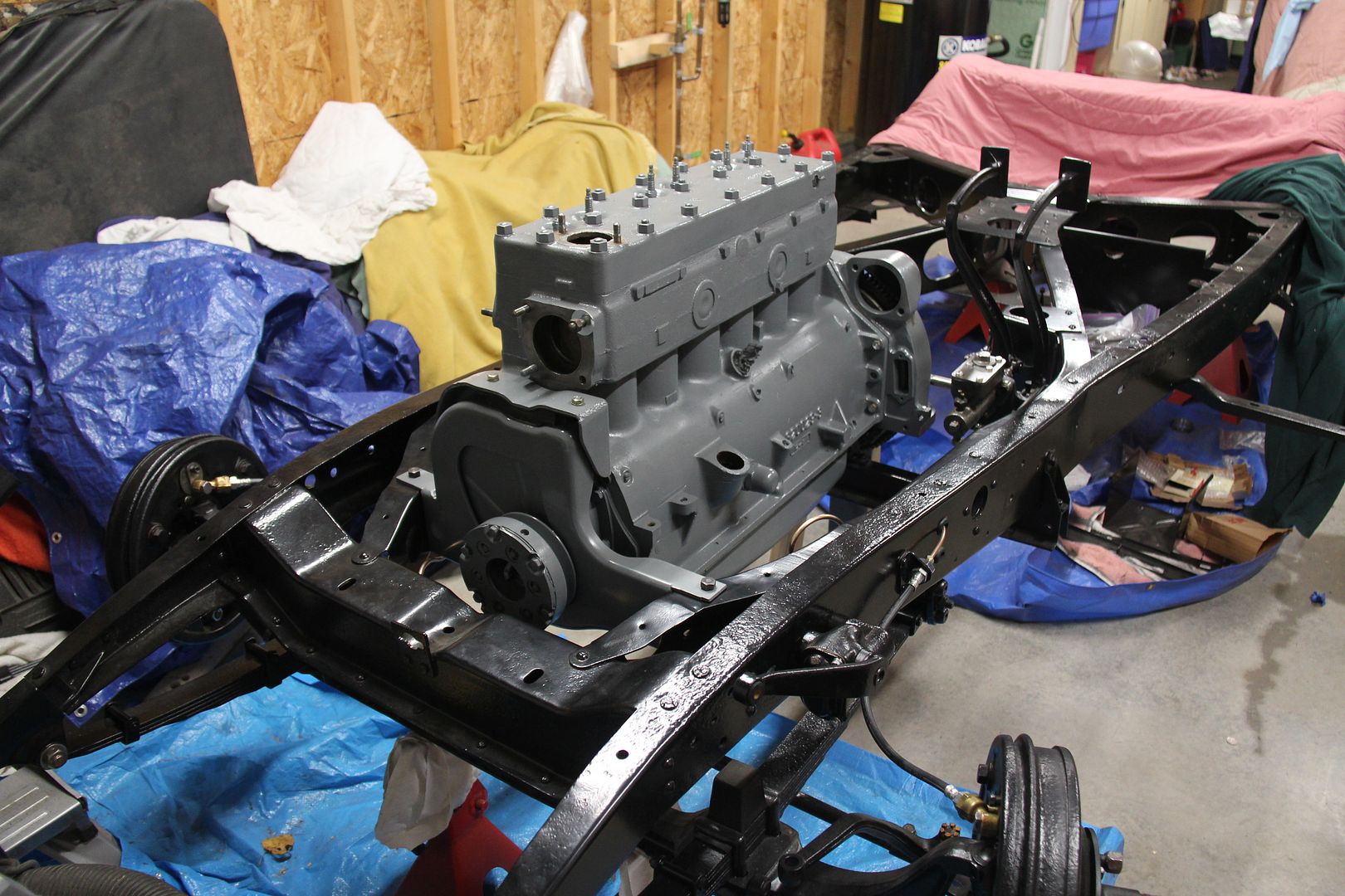
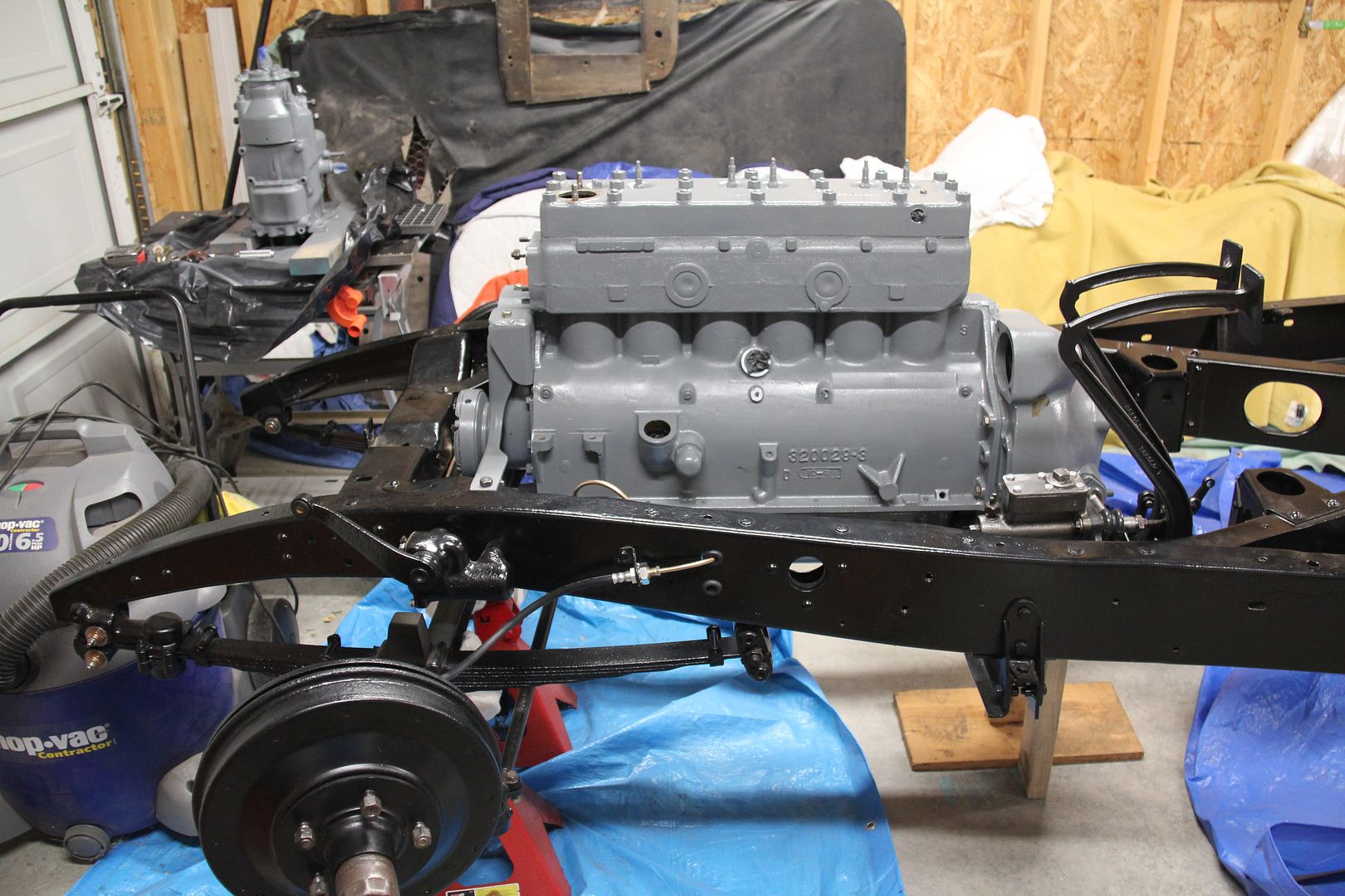
Long, long day today. My lovely wife Kathy joined in on the fun - I never would have gotten this done without her help. We got the engine off the stand on onto the lift, padding everything to keep the new paint unharmed.
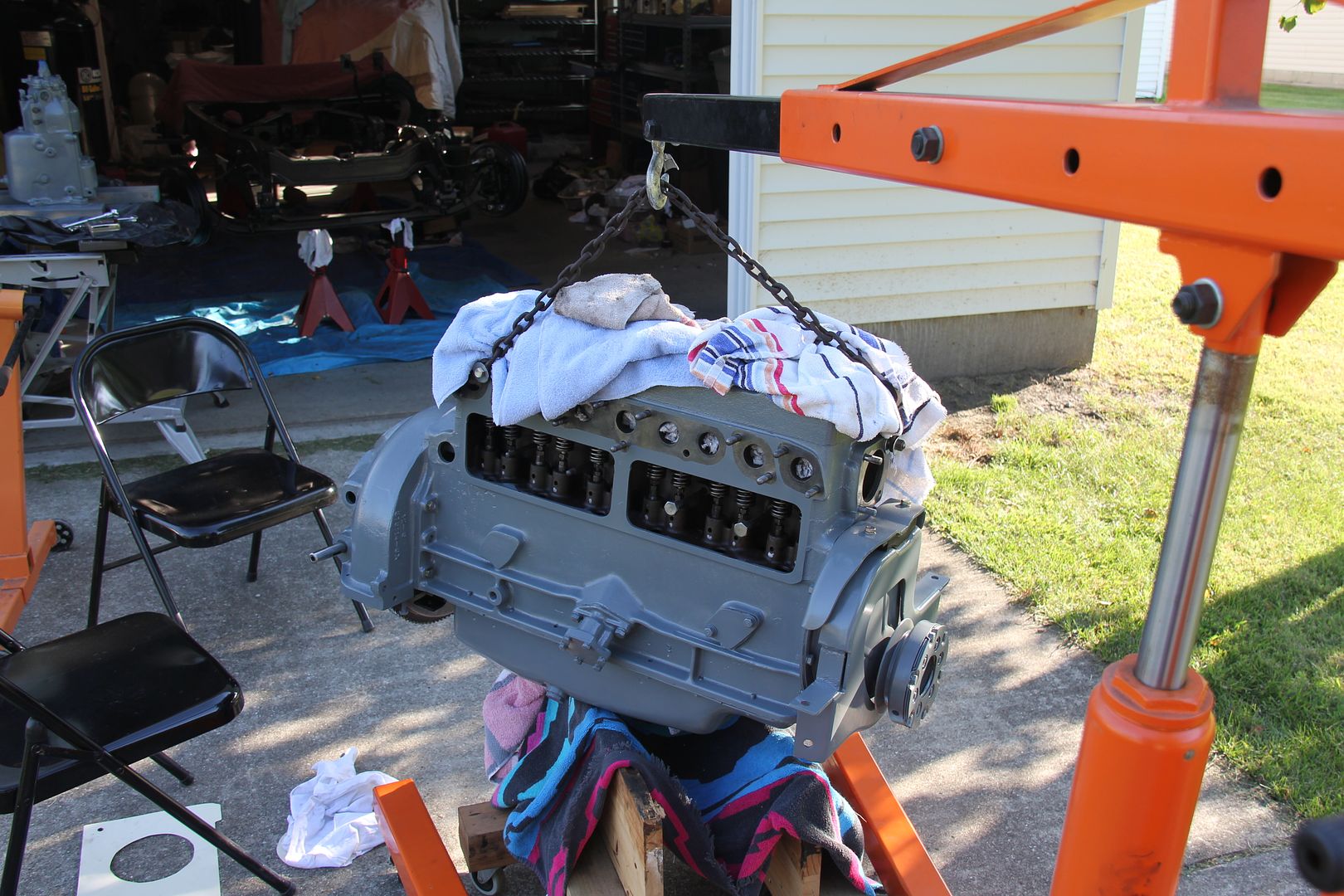
Installed the bell housing, flywheel, and clutch. Had a moment since one side of the clutch disk sticks out more than the other, but saw that the longer side interfered with the flywheel bolts, so that went toward the rear.
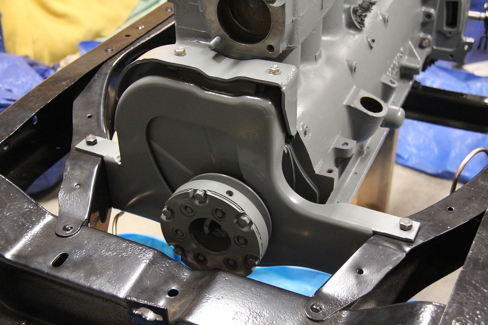
Installed the front motor mount cradle with the newly vulcanized rubber Floating Power mount.
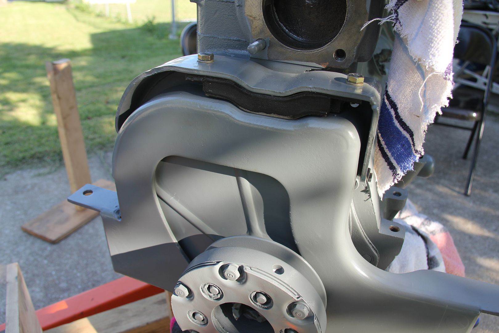
The motor dropped right in. I'm using some wood braces to keep the weight of the motor off the rubber mount just behind the oil pan. Still have the transmission to put in.
-
I don't know about being a teacher - most of the stuff I post is based on information I get from folks on this site. But thanks for the kind words.
-
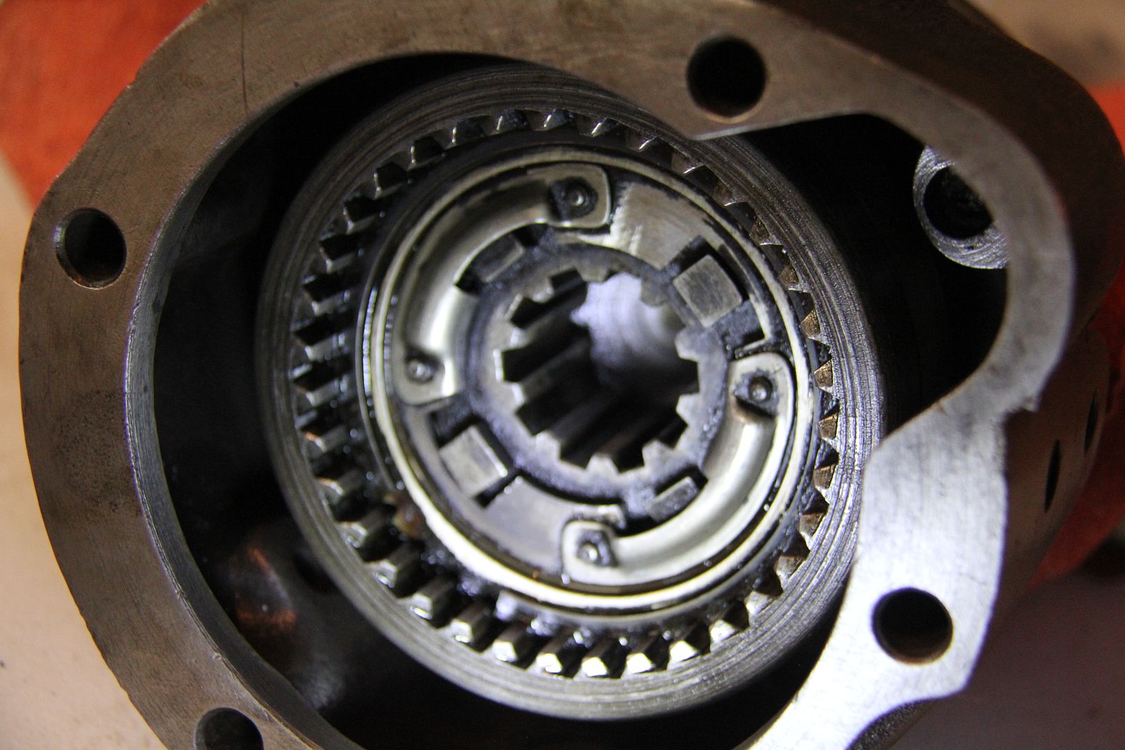
You're absolutely correct, Spinneyhill, the unit from the spare transmission turns freely in one direction and locks in the other. My unit would not turn in either direction and was totally locked up. I took the "lump" in my unit apart. It is similar to what you described. There is a center piece with ramps. At the start of each ramp is a solid piece that connects to a floating piece via a spring. The floating piece cradles a large roller and a smaller roller sits next to that.
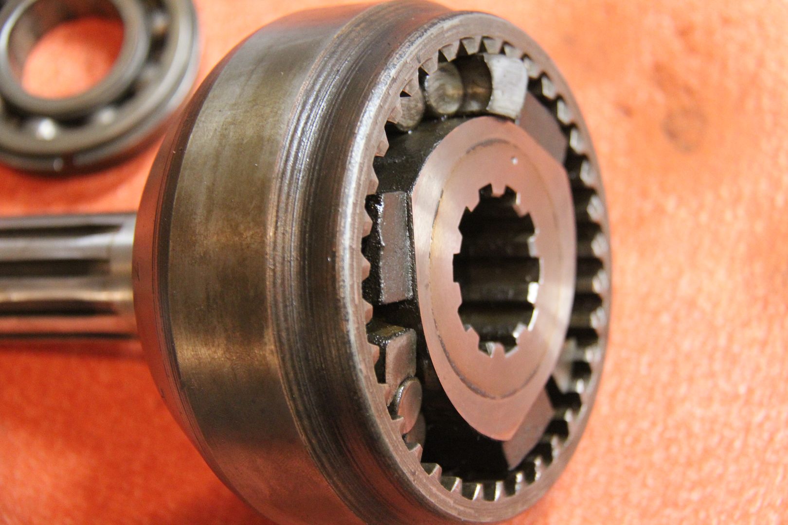
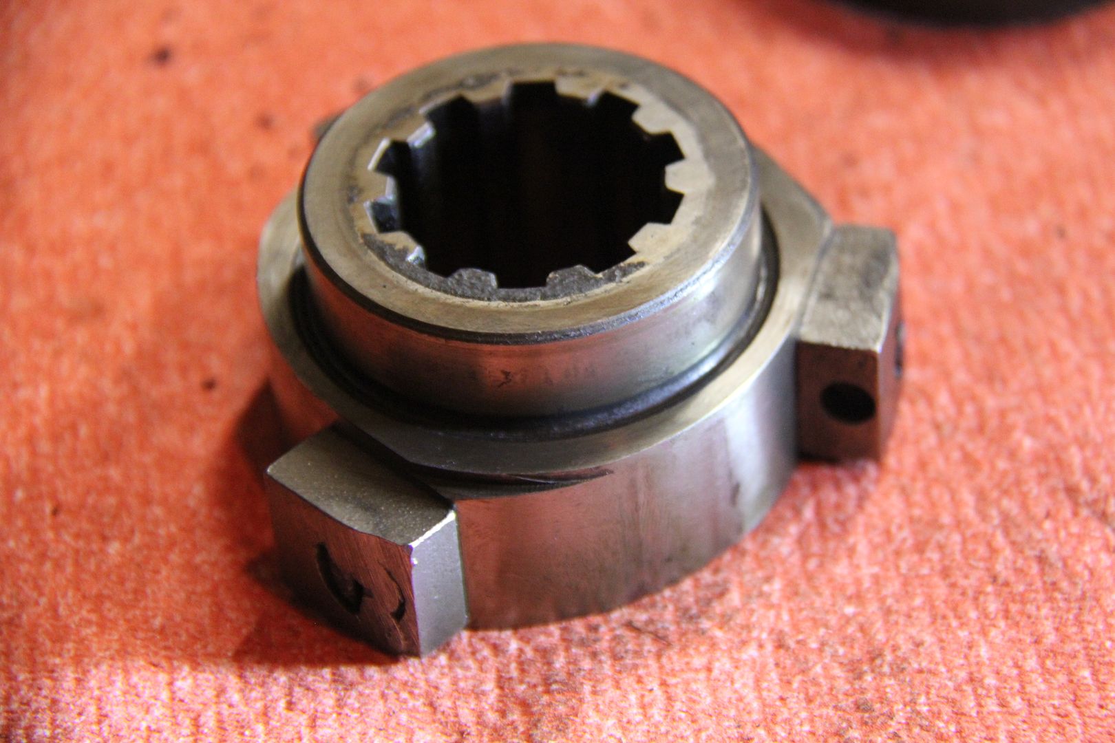
With everything removed you can see the bearing inside that allows the center piece to rotate.
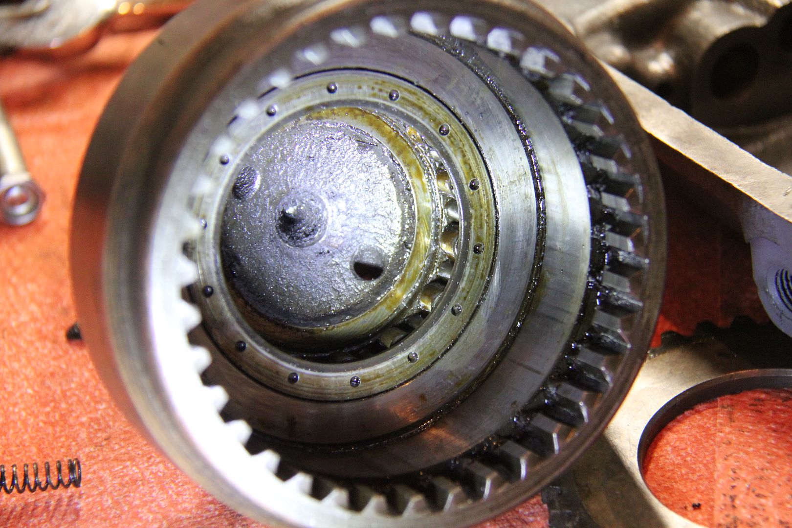
The center piece was full of crud.
I cleaned it off and discovered that there was some galling on the surface of the ramp where the rollers had scored the ramp surface.
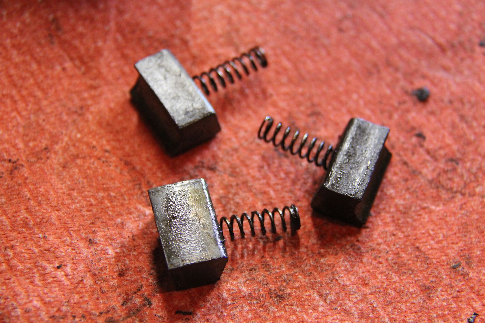
Here are the floating pieces and the springs.
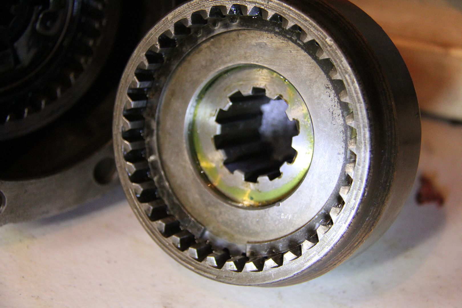
I couldn't find anything else wrong so I lubed everything and put the unit back together. Now it turned in one direction and locked in the other. However, the replacement unit will turn by hand if I reach in, while my "rebuilt" unit would not. If I put it on the mainshaft I had enough leverage to turn it, but but it was much more difficult than the other unit. It also made some noise while it rotated and I believe it's being caused by the rough ramps inside. The replacement unit spins smoothly and quietly, so I opted to go with it instead. It's a bit different, as I said before, but still fits perfectly and operates correctly.
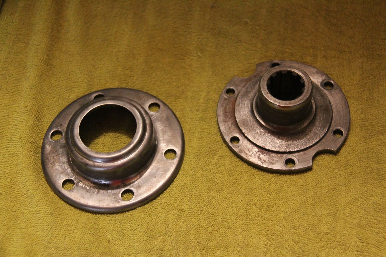
Here is my original unit.
And the replacement.
So, I finally have the transmission finished and painted. now on to the next catastrophe!


Fan Hub Failure - Your Thoughts??
in Dodge & Dodge Brothers
Posted
I agree, I think the weld let go.