


cutdown
-
Posts
232 -
Joined
-
Last visited
Content Type
Forums
Gallery
Events
Everything posted by cutdown
-
Thanks Guys. Chris, I will have another good look at this clamp of mine and get back to you [ mine appear to have the wording stamped into them. I seem to have put my sample in a SAFE place so will have to go back to thew car to look at another one. ] Yours look very much the same. Where abouts are you. I'm in Kerikeri. Sorry about the late reply. I forgot to recheck this thread. I have been busy sorting out these two engines of mine. Dereck How much postage would you like and how do I pay you. On close inspection of the photo, I can see part of the M and most of the R so they have to be the same. Mainland rings a bell but Summerland doesn't, unless you are taking the Micky out of Tim. Many thanks.
-
On my doges engines the dippers are protruding down on the con rod caps. The hole in the cap for the oil is ahead of the dipper relative to engine rotation. Not sure about the horizontal engine but perhaps in your case the hole in the rod should face into the direction of rotation as well. If the piston is laying behind the crank case [ relative to the vehicle axis ], then it would suggest the hole go to the bottom. Maybe the con rod nuts are supposed to contact the surface of the oil in the crank case. Not sure how your engine works. Something to think about. [ the oil level maybe critical in your case!! ] Is it possible there was a removable dipper the fitted under the head of the bolt in the con rod? Dereck
-
A very informative thread. I looked at the whole thread over a couple of days and was most interested in the pin-striping, babit metal and line boring parts. Also someone mentioned about a car having the dippers on the rods removed and causing it to wear out quick. My original engine in my 23 dodge didn't appear to have dippers. I had another engine so I stripped that as well. It had dippers as part of the con rods so my original engine looks like they ground them off. After measuring the bores I found three cylinders had 7-8 thou taper and one had 16 thou taper. [ all standard size even after 98 years ] The pistons had 4-8 thou taper between the area under the rings to the bottom of the skirts. I wouldn't be surprised if it smoked like hell so the removed the dippers to reduce it. Who Knows. Harm, you have so much gear. I am jealous. All I have are my motor mechanic skills plus a lathe, portable boring bar and welders plus many hand tools. I wish you luck with this restoration. What you have done so far is amazing. Dereck
-
My 23 dodge was modified to be a flat deck truck many years ago and the rear wheels were changed to 21 inch,. I am missing one wheel clap and bolt like this. Hopefully I can get another one rather than make one from scratch. I have no idea what vehicle is we off. There are 5 clamps on these wheels. many thanks Dereck


-
You could be right. Austins used two be two a penny in NZ. Worked on so many myself.
-
Perhaps I should have asked if anyone can identify what make of vehicle the smaller chassis number came off.

-
Chassis Number. Car Number. What is the difference
cutdown replied to cutdown's topic in Dodge & Dodge Brothers
Done. many thanks for the suggestion. 30DodgePanel Dereck -
Can anyone identify the small chassis number shown in this photo please.

-
Chassis Number. Car Number. What is the difference
cutdown replied to cutdown's topic in Dodge & Dodge Brothers
When I bought the car, those two plates were handed to me. [ not attached to the car ]. I had worked out from the car no that it was probably built on 18/05/1923. The small chassis number was sitting on the bottom of my security box where I kept all documentation, and I only found it yesterday I was not even sure of the exact placement of these tags, so hopefully someone can let me know. Many thanks for letting me know where the chassis number ought to be. I will check again when I am back at the garage.. I presume the tags are from Different cars then. There is a truck in a museum 70 ks north of here so I could ask what type of ID plate is on that. Dereck -
Hi. I just discovered my car Number of 905830 and then found a chassis number of 252573 in the same colour. They were both given to me when I purchased the vehicle in a semi finished state 36 years ago. They are quite different. Is there a reason for that or is it possible they are not from the same car. many thanks Dereck

-
Need advice on stripping down chassis
cutdown replied to 22touring's topic in Dodge & Dodge Brothers
Why Powder coating. We used to do it on our motorcycles with powder coat, but if it is chipped, and water gets in, it migrates. We are now using 2 pot paints to do this. It is harder and more resistant to chipping. I did see one of our members showing me an aluminium bar that had been painted with a special paint [ called Valspa 510 ]. He hit it hard with a hammer and it didn't chip. He was using this paint to paint buses. . I suggest you get some advise from someone who has firsthand experience with the different forms of painting/coatings. Dereck I had my 750 frame powder coated years ago. When finally rebuilt, I went for a ride. later, when I took the tank off, I found I had not used enough padding between tank and frame so the tank had worn the power coat off in one place. I cut a hole in a piece of paper just bigger than the worn area, and used a rattle can to cover the missing powder coat. -
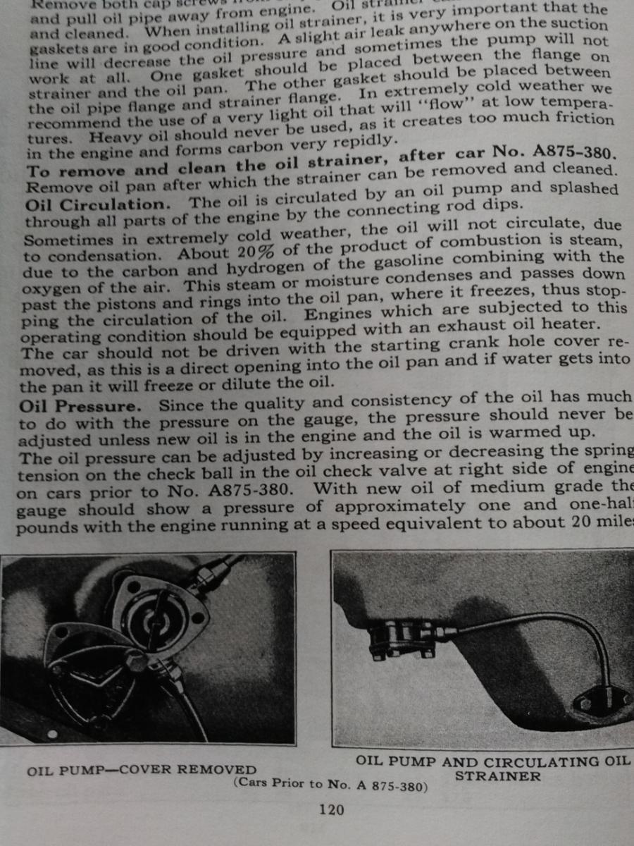
This time a question about Dyno chain and engine ID. First, My chassis plate is 905830, but according to page 103 in my manual, it refers to engines after A875-380 having timing chains. Mine definitely does not have a timing chain, but meshing gears so it has to be from a car prior to that chassis number. [ surely ] Second. On the page shown below, it says that there are 2 different Dyno chains, but it is very unclear from the description, which is which. Mine is joined by a pin which goes through quite a few interlocking fingers. Both chains refereed to have a single joining pin. so which is it. The older chain connected together by double link locked by a pin passing through both link pins.. "The new type chain has a connecting link which is locked by a pin through only one of the link pins" Mine is a Morse type silent chain, . If I understand what is written, the earlier chain is a convention chain, which is more commonly used now days. Its true, a picture is worth a thousand words and eliminates any misunderstanding. Hopefully someone may be able to shed some light on which timing chain I have because according to the manual, "the later type chain require tighter adjustment", whereas the earlier chain requires 1/2 inch up and down play, midway between sprockets".

-
Hi there. Someone on this forum asked about machining quite a bit off the head to increase compression. [ Sorry, I cant find that thread again ] . An answer to his question was that unless the cam was ground with a more modern grind, it was a waste of time. Also when I checked the manual, it said the exhaust vale closed at TDC and the inlet valve opened 8 degrees after TDC. I checked my engine before dismantling and using an "eyeometer" observation, I agreed with what the manual said. That valve timing is really backward for an engine. My intention was to make the car a bit smoother to drive based on the above and also to possible make the vehicle a bit more economical. Looking at the design, I would think it lucky to get 10 miles per gallon, but that is a guess. There was also talk on that thread that "hotting up'' these engines was not too detrimental. Not my intention though, as the vehicle is 98 years young, and the crankshaft is pretty spindly compared to modern engines. My experience on flat head engines is my very first vehicle. A CC Bradford van, which if I was lucky, Might do 25 MPG. [ Riccardo head design as well.. Basically a flat portion above the piston and most of the space above the valves and sloping down to the piston area. Spark plug between and beside the valves. ] My 4.2 litre Jags could be made to do 21 Mpg. I kno which I would rather drive. I am just going to be happy to get this car going again after sitting idle for so long. Adjusting the bearings was my priority, but after seeing how much black crap was inside it and how loose the front gears were, there was no option but remove the engine. It has a straight bore and Alloy pistons. Rings look in really good order. It needs a valve grind and renewing two exhaust vales as they had corroded on their stems. Also the welch plug at the back of the water jacket looks like it may have been leaking. The fan drive pulley has flogged out, water pump, Magneto, carb and lift pump unknown. Exhaust is ok for now but the flange nut is just about worn away so for now, I removed the exhaust in one piece. A new nut will be ordered as my spare engine is much the same.. I found there were no gaskets behind the valve covers and some of the tappets had not been tightened. It will be fun again making all the new gaskets. All the best. I have made the adapter for the drain plug. just a note, modern engines have a filter mounted to the oil pump, which is inside the engine. The old idea of cleaning the oil filter was because the oils available 100 years ago were not up to the job. [ hence the black crud found inside the engine. ] Picture here which also shows the old collet retainer and the crank pin. Dereck

-
I borrowed the 1 inch x 24 thread cutter and 5/16 unf tap from the mens shed, cleaned out the thread on the cam thrust pad and cut the thread on the front of the crank. I had a friend hold the engine while i refitted a 5/16 bolt attached to a chain which was bolted to the end of an old truck rear axle [ bloody heavy ], which is used as an impact puller for extracting hubs etc from cars. I gave the cam plug a bout 6 goes, finally giving it a huge heave and the bloody plug would not budge. i have now decided to leave the cam in place and to hell with sorting out a more modern grind. I machined the new nut today and double checked that the crank handle would go over the machined part loosely. All looks good. I machine a small taper where the nut cam neare the oil pump drive gear, and machined the other end down [ in silver ] to allow the crank handle to go over it loosely. Later when rebuilding the engine, I will shim [ the key way areas ] and loctite the gears in place after first working out where the nut will finish up. I will then mark the nut in the area where the crank handle pin goes and cut a hole in the nut to fit the pin. This will act as a locking devise for the big nut. I got sick of getting black hands again so got engine degreaser and a 12mm paint brush and took to all the surfaces that are hard to get at, like above each main journal and around the cam. All those lower surface ares were full of black crud. That"s the best I can do apart from running the engine on diesel oil for a few miles to clean it out. I had another thought today looking at the crank handle and the front mount tube. Ideally, a bearing would be best fitted to locate the crank handle better in the tube. Easy to do. get a bearing with out ID of approx 40-41mm and an ID big enough to go around the bends in the crank. Make up a tight fitting spacer to fit around the crank handle and inside the bearing. Split it and the drive it into place. Dereck

-
I CHEATED, I just went back around to the garage where my Dodge is being worked on and dragged the gearbox from behind the car up to the front where I can look at it. Looks like you disassemble the clutch throw out to remove the clutch. I also suspect that the flywheel spigot bearing takes all the forward thrust when you are pressing the clutch down, That's not the best idea and definitely not a good idea to ride the clutch. Thanks for the info on the early car. Dereck
-
HI GUYS. 22touring My son-in-law suggested removing the body, but that meant removing the tray first plus whatever else I would find along the way. Nah. Not so bad getting the engine out after following the above procedures, as well as removing the cyl head, and also the rear stud.I had removed the head some years ago. That early Dodge must be different from ours as i believe you can get the w/pump off in place. My project has never had front guards on it since I have had it so thaT may make it easier!! I didn't take mine off till I got the engine out though. I removed the magneto though for safety and easier access. Minibago Yes, I got an old unf bolt and wound it in back and forward for about three threads. threads were damaged so I do need a tap. I finally got the main bearings adjusted this morning. i thought i was going to be in the shit because someone else had used paper shims as well the the spacers to get the adjust right previously. i had found all sorts of crappy work done previously. Some one had in ingeniously filed some of the big end shims tapered to get the clearances right and both side were not the same thickness in some cases. Took the bolts out of the cam wheel this morning and found the cam and shaft had location timing marks. Its interesting that no timing marks correspond with TDC, the cam wheel to crack gear are timed 45 degrees or so away from TDC. A lot of work so far and much more to do. I still haven't had time to work out how to get the clutch off the gearbox but that will be soon. I have purchased a new flywheel spigot bearing locally. I noticed one of the rear wheels did not have a mounting lug or bolt so I need to get another one of those. It has been converted to 21 inch 5 stud at the rear and the lugs are different from the front ones. I will take a photo shortly. Got called away for lunch. Look at your nose she said. Go and wash it. Big black mark from the internals of the engine. Teach me to be so nosy. I cant wait to strip it completely to enable thorough cleaning. I took the end plugs out of the oil gallery and ran a wire through it to see how much crud was in there. A bit at the back but not too much that a thorough clean will fix later. Dereck


-
Slowly getting there. I feel like Captain Cook must have felt in 1769. He knew he was going somewhere, but had never been there before. In the top picture you can see the camshaft thrust plug on the rhs of the block. It looks like a 5/16 UNF thread in the middle for extracting it. Trouble is, a 5/16 unf bolt wont go in ans as we are in lockdown, I have no access to w 5/16 unf tap to clean the threads if necessary. Can anyone please tell me if it is 5/16 UNF. Also is there anyone out there that has the experience of stripping down engine, g/box and diff on one of these. it would be nice to get an idea in advance rather than the learning experience I have been though so far. I am a qualified Auto engineer but like Cook, I am feeling my way using the guidance of the Dodge manual which is not quite so easy to follow. Especially as when it comes to removing the engine etc it basically assumes you know what you are doing. Instead of removing the diff, g/box then engine over a 3 -4 day period, someone who knows what they are doing and so long as everything un- does easily, it should really only take 1.5 to 2 hours.. The manual does say remove the diff first, then the gearbox then lower the rear of the engine to allow getting the engine back out of the front cross member before removing engine. engine. The two 1 inch x 14 TPI nuts I ordered on Friday 13th, actually arrived yesterday. You can see in the main picture, I have removed the crank pin and the oil pump drive collet. I just have to wait until after our lockdown to borrow the thread cutting tool for the front of the crank. Someone mentioned on another thread about getting the cam shaft reground to get the valve overlap more modern. I would appreciate more info on which grind to go for. Dereck PS you can get an idea how dirty the inside of the engine is from the main picture here.


-
I agree. I have been thinking about this so had another look today. The front sliding joint is no problem and the cross member has plenty of meat in it to elongate the holes backward. Once I have the engine about to be fully installed, I will check the alignment and work out if I need to weld the front edges of the holes so it cant move. I stripped more of the engine and notice the pin holding the Morse chain together is extra long. It doesn't seem to have been a problem though. I had a better look at the front crank problem. Hmmmmm!!! Not much room. Was there a special jig made to enable the correct alignment of the clutch?
-
Yes. Vibrations. I will have to see if I can shift it forward. Not sure if the rear engine mounting will allow that but I could always look at reshaping the fire wall. [ Maybe ]
-
Its finally out. It was an interesting project working out how to do this. Lots of dismantling. Because the cylinder head was firmly against the fire wall, it meant I had to remove the rear head stud as well, which finally let go this afternoon. I head removed the head on an earlier occasion. One of the head studs broke so will need to get another one of those plus need to get more head nuts as there were a few standard thin nuts holding the head on when I got the car. Once I had removed the steering box, I could remove the exhaust complete with manifold . That manifold nut was too hard to get at in place and I will need to make up a special tool to fit the nut. Now to sort out the loose front gear problem. If its possible, I will cut a 1 inch UNF thread on the front of the crankshaft and make up a special nut to hold everything in place. Could someone please let me know how much clearance there normally is between the head and the fire wall? It could be that the body has been mounted slightly forward on the chassis. all the best. dereck
-
Hi Mark. Most of the camshafts I have worked on in the past which have been secured by bolts, don't have keys. Some have vernier adjustments as well. [ ie Jaguar ] I have had another look at my loose gear problem and decided to get some advice about threading the 1 inch portion of the crankshaft so a nut can be used to secure the gears. There isn't enough room for a mod to that collet. Also, the collet OD is about as big as you can go, without interfering with the oil pump driven gear which looks in my case to be forward of the centre line of its mate on the crankshaft. It will mean the nut has to be turned down sufficient to miss that gear when its tightened up. the drive pin for the crank handle can be utilized for some sort of locking device for the nut. Engine out before that happens. It will be good to do a total strip now to remove all that black crud inside the block. Thanks for all your help guys. i will keep this thread going as progress is made. Dereck
-
Hi Minibago. Could you please let me know the diameter of the crankshaft where the timing and Dynamo gears sit. It looks like Dodge must have known about the gears coming loose and decided to put 2 keyway's in the crank instead of the usual 1 keyway. [ My guess ] Picture of car just before putting in my daughter's garage. It does look odd withe 24 inch wheels on the front and the 21 inch on the back but that's the way I intend to keep it looking at this stage.


-
Hi Mark. The camshaft "drive gear" I mentioned, is the one on the crankshaft. The "driven gear' is on the camshaft. [ auto engineers terms ] Jack, thanks for your comment. I have never run this engine, but the bloody workshop manual I bought, mentioned that no pressure at idle hot was OK. To me that's a pile of shite. Below are pictures from the manual I bought. You can see in the middle of page 3 where it says no oil pressure is OK @ low revs. [ That's bollocks to me, unless I am Miss-reading what it says. ]

-
Jack. Look at the front of your crankshaft. You can see the drive pin which the crank handle engages. Behind that is a coller, which is held in place by the 0.2 inch pin mentioned above. That coller presses against the oil pump drive gear which presses against the Dynamo drive gear and the camshaft drive gear. I advise you to make sure any of those gears are not loose/. [ rocking or oscilating back and forward on the crank. ] If they are, you had better fix them as the workshop manual mentions a knocking noise they can make and also, destruction if they come loose. At the moment, I don't have the front off the engine as my original intention was only to adjust the bearing clearances once I removed the sump.
-
Minibago. That's a great help. Looks like a parallel hole. It also looks like the gears on your crank there have been moving as well. Must be a common problem. An engineer I know came to the same conclusion as me. Make a longer collet and thread the outside. Secure a nut over that to compress the gears, after renewing both keys and Loctiting the gears to the crank. That's the second odd dimension I have seen so far now. The squares on the rear sump bolts are neither metric nor imperial..Bigger that 3/8 and smaller then 7/16. 10.25 mm or 0.4035 inches. I always though american dimensions were in inches but didn't realize they used the decimal inches rather that the fractions. [ maybe apart from crankshafts and pistons ]


