Mike Macartney
-
Posts
1,300 -
Joined
-
Last visited
-
Days Won
1
Content Type
Forums
Gallery
Events
Everything posted by Mike Macartney
-

My 1910 Mitchell "parts car" project
Mike Macartney replied to JV Puleo's topic in Our Cars & Restoration Projects
Manifold looks good. I like the expanding mandrel and have never seen a centre finding tool like the one you are using in the photo. Very clever. -
REPORTS ON A 1914 HUMBERETTE RESTORATION
Mike Macartney replied to Mike Macartney's topic in Our Cars & Restoration Projects
I think I have fallen in love with the car too. It reminds me of a child's pedal car for grown ups! Today, I hope to spray the epoxy primer on the wooden parts. As I have never sprayed this paint before I am a bit apprehensive. -
REPORTS ON A 1914 HUMBERETTE RESTORATION
Mike Macartney replied to Mike Macartney's topic in Our Cars & Restoration Projects
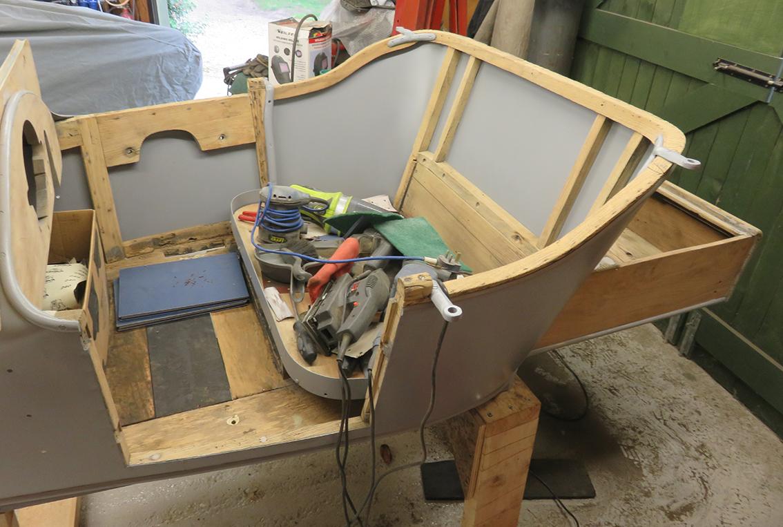
The last part of the gearlever surround is screwed into place. The old bit of wood on top of the upright was refitted with glue and screws after I had spent a few hours removing the tacks from it. At least now the coach trimmer will be able to put fixings into this upright. Some CT1 adhesive was also used to glue this split in the wooded bulkhead. Cling film was laid over the adhesive to stop the G-clamp sticking to the wood. Apart from some tongue and groove for the boot floor and a couple of other small bits of wood repairs the body is ready to be masked after a good clear up and clean down before the Epoxy primer is sprayed on the outer wood work at the back, the dashboard and windscreen mounting just behind the scuttle panel. Starting to mask up for painting. I bet I've missed a few holes in the woodwork to plug!


-
REPORTS ON A 1914 HUMBERETTE RESTORATION
Mike Macartney replied to Mike Macartney's topic in Our Cars & Restoration Projects
This is a photo of what we started with around the gearstick lever. Two thicknesses of 3/4" ply had been roughly sawn, screwed together, hammered into the gap and bonded with wood glue and then bodyfiller. Before completely removing this 'bodge' I made a template to locate the hole for the gear change so that after the body was removed from the chassis I could locate the exact position that gear lever protruded through the hole. Eventually the new part would need to be made in two parts. I started marking location points on this template A, B and C so that it could fit back in the same place when the 'bodged' bits of ply were removed. Reference point B is not in the above photo, but it is in the photo below. The floor was marked with a white marker pen at A, B and C so that the template could fit back in the correct place. I used a soft pencil to mark the area of the hole after the old plywood parts had been removed. Before the body went off for blasting I taped some clear plastic sheeting over the A, B and C marks on the floor so they would not be removed by the blasting process. The best laid plans did not work out like this! When the body came back from blasting there was only mark A left on the floor. This did not prove a problem because the template still lined up with mark A and the edge of the seat base. Now we go back to cutting out the bad bit and making bits of wood to fit around the gearlever. Robert made this small jig for making the rebate in the floor so that he could easily see when he had chiselled out the wood to the correct depth. This vibrating saw blade made cutting off the wooden blanking plugs in the screw holes a ''piece of cake'. It was also invaluable for chiselling out the rebated area around the gear lever. Robert had already made the parts to blank off around the gear lever out of some old oak he had. The first part seems to fit. These bits of oak need to be removable so that the gearlever, attached to the chassis will fit through the hole in the floor. Just checking that the new bit of wood is in the correct position. The upright at the side of the seat were the rotten wood had been removed was ready for the new part to be glued and screwed into position. We used CT1 adhesive as it would grip into the uneven surfaces. The new wood tapped into position and screwed into place.


-
REPORTS ON A 1914 HUMBERETTE RESTORATION
Mike Macartney replied to Mike Macartney's topic in Our Cars & Restoration Projects
It seems to be a while since my last report. I am still pulling out upholstery tacks! About an hour at time is enough. I have found that if I first use a hammer with a small hole punch over the head of the tack, then tap the head of the tack backward and forwards with a small chisel to loosen it, the modified pliers will then grip the head of the tack and it can be twisted, loosened and pulled out. Sounds easy, but when you have so many tacks to remove it gets rather boring. Wood work - Roberts vibrating saw blade made easy work of rebating the area around the gearstick to fit in some new wood. I put some tape on the blade at the required depth so that I could tell him when the cut was deep enough. Previously, the area had been 'hacked out' and some bits of plywood 'gobbed in' with glue and filler. Roberts idea was to make some inserts to fit neatly around the gearstick mounting. This was to be made in two sections each side of the gearstick. I'll add some more info this afternoon.
-
My 1910 Mitchell "parts car" project
Mike Macartney replied to JV Puleo's topic in Our Cars & Restoration Projects
You are correct in your assumption. I never knew that there was so much interest in arms in the UK. Thanks for your drawing of the oil pump and I look forward to reading more in the future. Keep up the good work. -
My 1910 Mitchell "parts car" project
Mike Macartney replied to JV Puleo's topic in Our Cars & Restoration Projects
Antique arms & armour: It sounds as if you have an ideal 'real job' which many of us would call a hobby! I was amazed to find so many books listed, many with your name mentioned, on the subject. All quite alien to us Brits, in the UK, where guns are not the norm. I am just writing an article for a cycling magazine, on our attempt at the human powered speed record, back in early 1980's, which was our first trip to America. I quote, regarding our first meal, on the first evening in a hotel, opposite Hollywood race track in LA …. we were chatting away and Alan said “What do you think those holes in the windows are for”. We all looked and could not think of any reason why there should be holes in the plate glass, there seemed to be no pattern to the holes. Eventually a waitress came over and introduced herself to us in a lovely southern drawl. We asked her about the holes and she said “Oh, people drive by on the highway and take pot shots at the windows, see the traffic lights over there, some one was shot there a few days ago”. Scary - we never sat in the window seats again! Oil pump body: I have yet to figure out what you are up to in the third photo. It will become apparent when you are further on with the machining of the oil pump parts. More than one project: What I meant was; that I only like to carry out one large project at a time. There maybe a number of small projects within the large project when I can distance myself from a problem, to give myself thinking time. Socket cap screws: You have surprised me too, with this page out of an old catalogue. I have purposely avoided using them in the past on old projects as I thought they came into use much later than pre World War One. -
My 1910 Mitchell "parts car" project
Mike Macartney replied to JV Puleo's topic in Our Cars & Restoration Projects
Thanks for all the useful information. I did have a look on the internet and found a lot of information. I now see how they work. I contacted Cronos in the UK who advertised them for small lathes on their website, they came back to me with 'not available anymore'. No problem, I can make a simple version from the information above and the information on the internet. The problem is always the time! I tend to get focused on one project and concentrate on that project rather than having more than one project on the go at the same time. At present it's getting the 1914 Humberette back on the road for the first time since it was last on the road in 1926. You have also helped me a lot with your drawing. I only started using Adobe Illustrator for drawing out 'stuff' this year (before it was old fashioned pen and paper). I have found I get a bit 'bogged down' with detail rather than using your method above using blocks which will make understanding what I am trying to achieve a lot easier. Mike -
My 1910 Mitchell "parts car" project
Mike Macartney replied to JV Puleo's topic in Our Cars & Restoration Projects
I look forward to seeing details of your radius turning attachment. I have always thought of trying to buy one, or make one, for my Myford lathe but do not know where to start. I suppose I may find some details on the internet if I looked. Keep up the good work. Mike -
REPORTS ON A 1914 HUMBERETTE RESTORATION
Mike Macartney replied to Mike Macartney's topic in Our Cars & Restoration Projects
Thank you for bringing up about the brass screws in the metal. I hadn't thought about that. The box of brass screws were there, so I used them without thinking. I will replace them with steel screws. Thanks for bring it to my attention. And yes, the Humberette door is small and light. It only has the one door on the passengers side. -
REPORTS ON A 1914 HUMBERETTE RESTORATION
Mike Macartney replied to Mike Macartney's topic in Our Cars & Restoration Projects
Back again! This is the panel that I made out of some steel and panel beat to shape to fit over the door 'tread plate' I suppose you would call it. It has a small downturn on the outside to cover the pins holding the outer panel on. On the inside I have made the downturn to come about an 1/8" above the floor. I removed the temporary screws, countersunk the screw holes and fitted brass screws. The 'HUMBER' name plate will cover the two centre screws. I will have a think as to whether I hide the outer screws with filler. At least this plate will stop the ash frame being worn away over time.


-
REPORTS ON A 1914 HUMBERETTE RESTORATION
Mike Macartney replied to Mike Macartney's topic in Our Cars & Restoration Projects
Robert did turn up and drag me out 'kicking and screaming ' out for a drink' on Sunday lunchtime. I lie, I was quite happy to be dragged away from pulling out old upholstery tacks! I asked him about screwing into end grain and he said he learned the idea of gluing in wooden plugs in old screw holes from an elderly carpenter, many years ago, probably in the mid 1950's. Robert agreed that it is not ideal, but is a lot better than just fitting a screw back into the existing hole. He said that best practise was not screwing into the end grain, but some times it was a necessity on an 'old project'. If it was a new build he would try and avoid it, but if the need arises you could use a longer screw with a courser thread, similar to a decking screw. When it came to plugging the door hinge screws and screwing into the end grain of the wooden plug. He says,, it can't split out because of the surrounding wood that the plug is glued to, will stop the plug splitting. His theory seems to have worked OK so far, on this Humberette project, plus the number of years he has been using this method with success. I have been looking at this bit of wood at the bottom of the door shut. When the body was in the blue gloss paint, this area of paint had cracked badly. I looked up the photos of other Humberette's and found the following photo. You can see in the photo above, that the woodwork at the bottom of this door shut on a Humberette has worn away badly, with the constant wear from being rubbed with shoes, from getting in and out of the car. I thought I would try and prevent this by fitting a metal covering over this area to try and avoid the problem in the future, I used some paper to make a pattern. Unfortunately, all the lines were curved, so I could not use a folder and would have to use my panel beating skills. I allowed enough metal on the outside of the body to cover the join of the outer panel to wood, but the join would still be hidden from sight by the door surround. On the inside of the body I allowed a bit more metal to cover the timber framing. The paper pattern was laid on a metal sheet and taped down to stop it moving. The 4 off blue marks are the screw hole positions to hold the panel to the wood. I centre punched these and marked around the paper pattern with a felt marker pen. If you look at the bottom of the paper pattern against the metal you can see the slight curve I was talking about. I used masking tape to give me a guide line to draw where the other masking tape had been holding the pattern to the metal. Now comes the tricky bit. Try and cut away as much of the black line as I can without cutting into the inside area that I want to keep. This electric sheet nibbler is good for jobs like this. I have clamped the sheet metal to a workmate. To finally smooth off down to the edge of the black line I used a angle grinder with an 80 grit flap wheel. Just checking it fits in the bottom of the door shut before beating the edges over. Again checking, that the plate will clear the bottom of the door without the door touching the plate when the door is closed. Looking for a photo of panel beating this plate and the trial fitting of the plate. I couldn't find any. I must have been enjoying myself so much that I got carried away with what I was doing and forgot to take any photos! I'll try and remember to take one tomorrow. Anyway I have used up my allowance of the 9.77MB maximum forum post. Bye for now.


-
REPORTS ON A 1914 HUMBERETTE RESTORATION
Mike Macartney replied to Mike Macartney's topic in Our Cars & Restoration Projects
Interesting comments above from forum members. My thoughts are that as the original screws have been removed and there is a hole left. It is better to fill the hole with wood and glue rather than just fitting another screw. Also, with the door the hinges, it meant that we could screw the hinges in the correct positions rather than the hinges going back in the positions that a previous restorer had fitted them. Robert may 'drag' me out for a beer or two at the Black Boys pub at lunchtime, if he does, I will ask him for his thoughts. If not I will ask him on Monday when we hope to, at last, split a quarter out of the tree trunk for making the top bows. This morning he said he was going to modify a chain for his chain saw with a 10 degree angle on the cutting blades rather than 25 to 30 degrees, so that the chain saw did not try to follow the grain on the trunk. I like the tip about the soldering iron on stuck screws. I'll give it a try next time I come across a stubborn screw. This is the worst bit of wood on the framing. If we left it, it would be difficult for the coach trimmer to fix to. We decided rather than replace the whole section, that would be very difficult, we would cut back and fit a new 'face' to this upright panel on the drivers side where there is no door. Before Robert started his 'woodworking skills' on this section I removed all the upholstery tacks that were embedded in the wood so that Robert did not damage his saws and chisels. Starting to cut away the rotten area, where damp and wood worm have done their worst. We are keeping the wood to the right that has the screw holes for the top (hood) frame mounting bracket. Cutting with the vibrating saw blade from the front side. Chiselling out the damaged area. At this point we came across a problem! Robert hit the end of a screw that was screwed in from the outside of the body that was holding on the beading on the outside of the panel. While he resharpened his chisel I used my Dremel tool with a thin cutting disc to grind away the sharp ends of the screws. Robert - how many tools do you need for this job?! You can see the dark areas where the screws ends were ground away. Just a bit more wood to remove and we should be there.


-
REPORTS ON A 1914 HUMBERETTE RESTORATION
Mike Macartney replied to Mike Macartney's topic in Our Cars & Restoration Projects
The work on the Humberette has gone further ahead than the reports so I need to spend a bit of time updating the reports. I have decided to get one wheel filled and in its last coat of primer before I tackle the rest of the wheels. After rubbing down the first coat of primer, on which I had sprayed a thin guide coat of satin black, it highlighted how much more filling was left to be done. After filling again with body filler and rubbing down with 120 grit on two of the wheels I wondered where the red colour was coming from that was beginning to stain the grey primer. Then I saw that both my thumb and index finger were bleeding. I had worn through my skin with all the friction from rubbing down. As my old dad used to say - "Where there's no sense, there's no feeling"! I only had some small areas left to rub down on one wheels so had a thought. I cut up a rubbing down block with the angle grinder, fitted with a 1mm cutting disc and used this thinner rubbing block to smooth down the areas between the spokes. It didn't work as well as the fingers on your hand but it saved anymore damage to my poor old fingers. Another few coats of primer and another black guide coat and I think this wheel might be somewhere near finished. Next I will use 240 grit production paper and see what it looks like with hopefully the last coat of primer before the top gloss coats. the colour of which is still undecided, Royal Blue, Black or something like the original Orange/Red colour? Now for something completely different while my right hand recovers! Robert came down to help me and give me my second ever lesson in woodwork. How to fill screw holes. No, he is not playing with a Cribbage Board! He split up some bits of wood with a chisel and then shaped them with a knife to plug the holes in the door and door shut for the hinges. He works so fast you can't see the knife! These are a couple I plugged latter on. Not quite as good as Robert's plugs. When the plugs are made, wood glue is put into the holes and spread around the inside of the hole with a bit of welding wire. The plug is then coated with wood glue and then tapped into the hole. The plug is left for 24 hours for the glue to set before sawing off the plug nearly flush and then smoothed off flush with a chisel or sander. Robert prefers a sharp chisel and I prefer a sander. These oscillating tools with a saw blade attachment are Ideal for this job. The next day, after fitting the wooden plugs, they were cut flush and the hinges were fitted. To mark the centre of the hole, I found a drill that would just go through the hole in the hinge. While the hinge was held up to the hinge post I drilled carefully, just to mark the centre and then drilled a small pilot hole for the new brass screw. One screw was fitted on each hinge at first, just to check that the door fitted properly. Thankfully, it did. This drilling and screwing was repeated for all the hinge holes on both the pillar and the door. It fits! And my door twisting and fixing brackets worked. I hadn't noticed before that the half round moulding at the top edge of the door is smaller than the moulding either side of the door. I have ordered a new length of correct size moulding to replace it.


-
REPORTS ON A 1914 HUMBERETTE RESTORATION
Mike Macartney replied to Mike Macartney's topic in Our Cars & Restoration Projects
Thanking Spinneyhill for his help regarding removing the old rusty upholstery tacks from the wooden framing. Rotating the tack, if the top doesn't break off in the process, works extremely well. If they do break off at lest they don't leave a sharp bit sticking out. I have also found that if I can't get to the top of the tack to grip it with my modified side cutters I found that using a hole punch that is just a bit larger than the tack head helps to get to access the tack with the side cutters to grip the tack and rotate it. If I still can't get a grip on the tack I have found that using a small chisel and tapping the tack from front back and sideways loosens the tack and this helps the removal of the tack. It seems to be a very time consuming job that you can only do for a short while before going 'cross eyed'! Using the hole punch to clear the head of the tack to get a grip on it. Got you, you pesky little tack! And out she comes. Only another few thousand to remove!


-
My 1910 Mitchell "parts car" project
Mike Macartney replied to JV Puleo's topic in Our Cars & Restoration Projects
It's looking very good. I am sure you are pleased with how it has worked out. I would be interested to know the price for ceramic coating in the States? When I enquired over here, in the UK, about having a couple of V8 exhaust manifolds ceramic coated, the price to me seemed very high. -
REPORTS ON A 1914 HUMBERETTE RESTORATION
Mike Macartney replied to Mike Macartney's topic in Our Cars & Restoration Projects
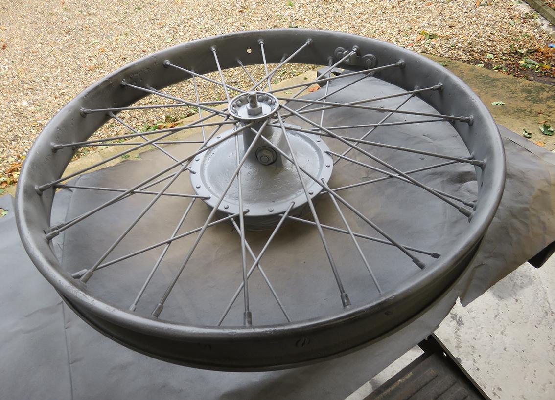
RE: RUSTY TACKS Many thanks for the ideas and the link. I will have a look and see what's available in the UK. And try your suggestions. RE: UNLACING THE WHEELS Yes, your right. That's what I should have done. I had originally thought that, maybe, I should take the rims and hubs apart. The idea of trying to rebuild the wheels again put me off. I have built bicycle wheels in the past I knew it would be a lot of work! If the spokes had been very rusty I would have had to do this, but the spokes on these wheels are in very good condition. -
REPORTS ON A 1914 HUMBERETTE RESTORATION
Mike Macartney replied to Mike Macartney's topic in Our Cars & Restoration Projects
No problem. I'll send you a message with my email. -
REPORTS ON A 1914 HUMBERETTE RESTORATION
Mike Macartney replied to Mike Macartney's topic in Our Cars & Restoration Projects
Jeff, I think I will send a photo of the tacks to the coach trimmer and ask him if he needs them removed. He may say he can work round them. I am worried that if I have to use a chisel to get to them I may do more damage than good and split the wood. I turned myself a small tubular cutter to put over the tack and hit it with a hammer to move the wood away from the tack so that I could get the modified side cutters in to grip the tack, but that didn't seem to work either. Thanks for your thoughts. Wood really isn't my thing, I only did metalwork at school so never learned the basics of wood. Here's some more stuff to add to my reports. Then at least the reports will have caught up with my progress. Brackets for the spare wheel mounting ring cleaned up well in the blast cabinet. There was a lot of rust under the paint. The ring took a lot of rust removal. It was just to large to fit in the blast cabinet. Right, I have had enough of rubbing down for today. I'll try painting this wheel with primer. The temporary bolt through the centre fitted neatly into a hole in the Workmate so that I could rotate the wheel to get to most of the rim. I am only going to paint the rim. Decided I would prime the other rim as well. Oh dear I think they are going to need some more filling. I sprayed a guide coat of black so that when I rub the primer down the low parts will be highlighted in black and I will see easier the area that need more filler. That's a job for tomorrow. I'll leave you with a young lady of the Edwardian era starting her Humberette.


-
My 1910 Mitchell "parts car" project
Mike Macartney replied to JV Puleo's topic in Our Cars & Restoration Projects
I'm no expert on brazing, but from looking at the photo it looks as if the brazed area has been heated to much. I find it difficult when brazing two bits of metal at different thicknesses. I'm told that the best way is to just put the flux on the areas you want the braze to flow and don't melt the brazing rod with the torch, play the flame on the thicker material and let the heat from the material being brazed melt the brazing rod. Easier said than done! I find nickel bronze welding a lot easier than brazing, although the rods are quite expensive. I am looking forward to seeing the manifold ceramic coated. -
REPORTS ON A 1914 HUMBERETTE RESTORATION
Mike Macartney replied to Mike Macartney's topic in Our Cars & Restoration Projects
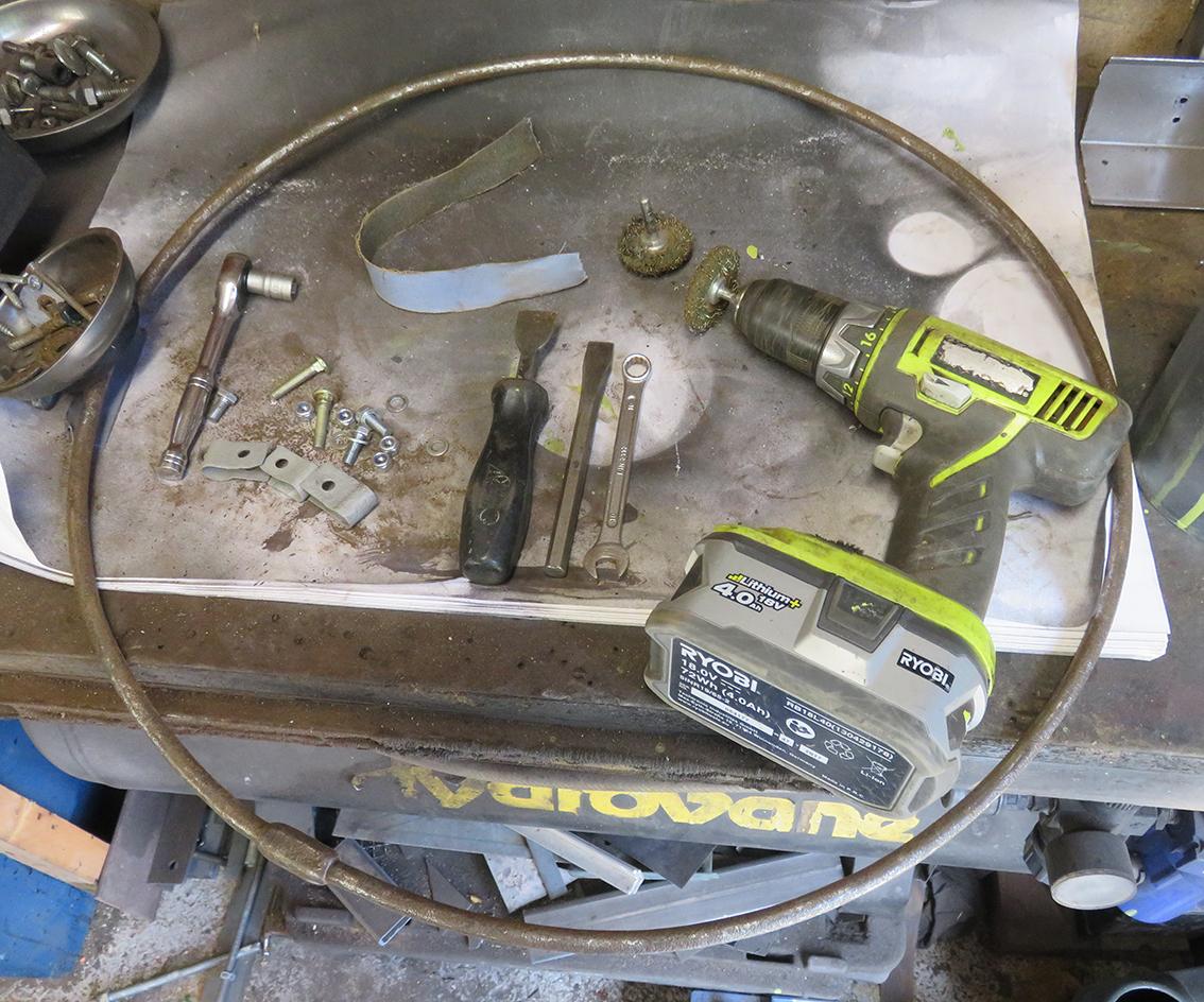
It's back to wheels again. You and I are all going to get up with the sight of spoked wheels soon! Two of the wheels are starting to get somewhere near to what I was after. I have been using 120 grit production paper to rub down the filler and the 2-pack primer. I would really like to finish two wheels to give my some idea what they are going to look like when finished. In addition, if two of the wheels look good, when compared to the two wheels I haven't touched yet, it may give me more enthusiasm for completing the refurbishment of the wheels! Just when you think you have finished rubbing down you find more bits to fill and rub down. I am using fine body filler as the pits and scrapes are not deep, but I feel they are too deep to use high build primer as yet. Buy way of a change I etched primed the other brass windshield support bar. Having worn out the ends of my fingers from rubbing down the wheels, I though I would have a look at the front wings, (I think you call them fenders?) and see what needed to be done to these. I managed to find proper wing bolts on eBay rather than normal coach bolts that the previous owner had used. The original type wing bolts have 1" diameter heads as can be seen in the photo above. I do not have a clue as to why there are so many holes in the wing near the front mounting? Perhaps the guy had a new drill and wanted to try it out?! More work for me to do, cutting out the excess holes and welding in new metal. I think I will also weld in a strengthening section under where the wing sits on the front wing mounting bracket. The rear edge of the wing where it bolts to the running board also needs some attention. This is the front wing on the left hand side. I am very glad now that I had the paint and filler removed by Soda Blast, as I would not have realised that this area had been so badly repaired. This will need a new section panel beaten, the bad section cut out and the new metal welded in. Hopefully I can make a better repair than this. Still suffering from sore fingers I tried the fit of the 'ratchet' for holding the outside handbrake on and the mounting for the 'Stepney Wheel'. I'll machine up new mounting tubes that are distance pieces between the body and the bracket and give them a bit of shape, rather than a straight bit of tube that they are now. The bracket also needs a bit of finishing off. I took this photo because I wanted to see if the bracket for the spare wheel needed any mods. Because the previous owner did not use any heat when he bent the flat bar the bends need to be tidied up. A bit of heat and a hammer should do the trick. The handbrake ratchet can be easily seen in this photo. OK, time for a bit more filler and a bit more rubbing down! Here you can see clearly what I'm up against! I am afraid these hubs are going to stay as is. I can't get my big hands in there to fill the pits or rub the filler down. Anybody got a small child that doesn't get bored easily! On to something different. This is a tool I bought for removing the upholstery tacks that are still in the woodwork. I thought I would try and remove as many as I could to make life a bit easier for the coach trimmer. I managed to remove the easy ones that still had there heads on, but I think when the original leather upholstery was pulled off it pulled the heads of the upholstery tacks that had gone rusty around the leather. I modified an old pair of side cutters so that I could 'dig in a bit' to the wood to get hold of the tack to pull it out - that worked on some, bit but in most cases just cut the top off the tack making it even more difficult to pull out the remaining bit of tack. Here is a close up. Any tack removal suggestions would be appreciated. There are plenty of these tacks especially along the back.


-
REPORTS ON A 1914 HUMBERETTE RESTORATION
Mike Macartney replied to Mike Macartney's topic in Our Cars & Restoration Projects
The modified scraper looked as if it would work well. By the time I managed to get round a quarter of one side of the wheel rim using a small spatula to put on the filler and the modified scraper to get the excess filler off, the filler I had mixed had gone hard! In the end I used my fingers to smooth the filler over the pits in the rim. At this stage with four more wheels to repair I would have been better off buying new rims and new spoked, if new rims had been available! I am finding it hard work rubbing down the filler on the wheels and trying to avoid getting any filler on the spokes or spoke nipples. You always come across these depressing problems with restoration work. Tomorrows another day and hopefully I may get on better than today! At least filling in these holes in this moulding was a lot easier. Where I have put a thin skim of filler in the left hand bottom corner of this panel there was a dent coming outwards? Strange, then I realised that the previous owner had fitted a small battery behind this panel, for the electronic ignition he had fitted and had drilled through the ash framing to put the earth lead through. He must have pushed the drill too hard and the drill point had dented the panel! Nearly finished filling all the mouldings. Problem I have just seen looking at this photo. The screws on the left hand side moulding in this photo go into the bit of ash framing that I need to replace - Oooop's! That's going to be fun trying to get the filler out of some of the screw heads! One reason I like doing these reports is it gives you a chance to look back at the work you have done and foresee problems. In this case, too late! This photo shows just how bad the pitting is to some parts of the wheel rims. The reason I decided to use filler was that if I had used high build primer it may have given me too much of a build up of primer on the spokes and nipples which would have been even more difficult to rub down. I have just found a photo of the filler spreader that I made up for the mouldings. The cut out section of the spreader was removed carefully with a cutting disc in an angle grinder. The better side of one of the rear wheels rubbed down. Only another 9 sides to go including the 'Stepney' wheel! Had another go with the shaped spreader and it worked better if I rubbed the filler in with my fingers and then scraped the excess off. I thought I had filled all the screw holes in the mouldings and then found these at the back. Bored with filling and rubbing down I etched primed the brass support for the windscreen and checked it still fitted. I'll leave it in this position for the time being until the new fixing screws arrive. This is the right hand one before 'blasting'. Hexagonal bolt heads just doesn't seem right with fixing these to to side of the body. I am going to use dome head countersunk slot set screws instead of the bolts. I think they will look better. A view of blasting the windscreen support (I think you call them windshields instead of UK word windscreen). This second hand Hydrovane compressor, Guyson blast cabinet and filter system is probably the most useful bit of kit I have ever bought. All for now - back soon.


-
REPORTS ON A 1914 HUMBERETTE RESTORATION
Mike Macartney replied to Mike Macartney's topic in Our Cars & Restoration Projects
I wasn't expecting Soda Blast Limited to prime the metal parts. I just asked then to etch prime the bare metal so that it would not go rusty between them finishing the blasting and me collecting the body etc. It was a nice surprise to find it in 2-pack primer. I suppose as they had masked all the wood up it was an ideal time to also give the metal panels a coat of primer. The spray job was better than if I had sprayed it! There are an awful lot of screw holes to fill! Now, with filling the rust pits in the wheels I thought I would be clever and make a scraper the shape of the edge of the wheel rim to enable me to put as little filler on as possible so that I did not need to rub off lots of hard filler. I used this tool to give me an idea of the shape of the edge of the wheel rim. I then transferred this shape onto a piece of card and modified the shape as required with a pair of scissors. When I was happy with the shape I transferred the cut out to the edge of a stainless steel filler scraper. I had already done this modification to another scraper for the mouldings on the body and it had worked really well. I will now keep you in suspense as to whether or not my 'special' scraper worked! To rub down the filler on the mouldings I folded some 120 grit paper into a 1" wide strip and holding between two fingers ran the rubbing down paper along the moulding to remove the excess filler without flattening the curve of the moulding. It worked really well. I then coated the filler and parts of the alloy moulding, that had gone down to bare metal, with etching primer. The moulding on this side was a different shape to the other mouldings and I decided to fill the holes using a spatula rather than making another shaped spreader. I wish I had made one because the filler on these was very difficult to rub down and the holes did not fill properly and I will have to put another coat of filler on them.


-
REPORTS ON A 1914 HUMBERETTE RESTORATION
Mike Macartney replied to Mike Macartney's topic in Our Cars & Restoration Projects
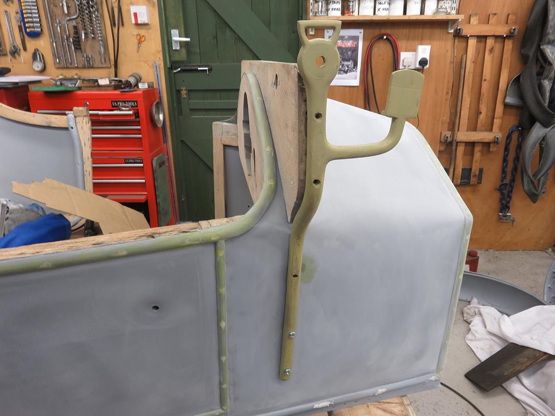
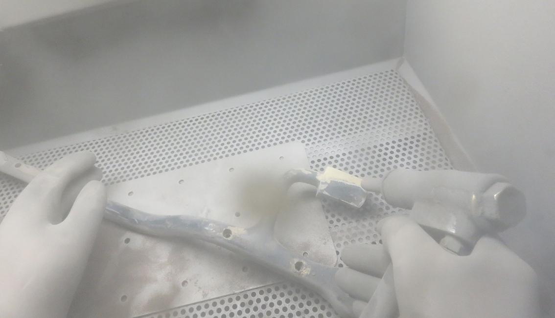
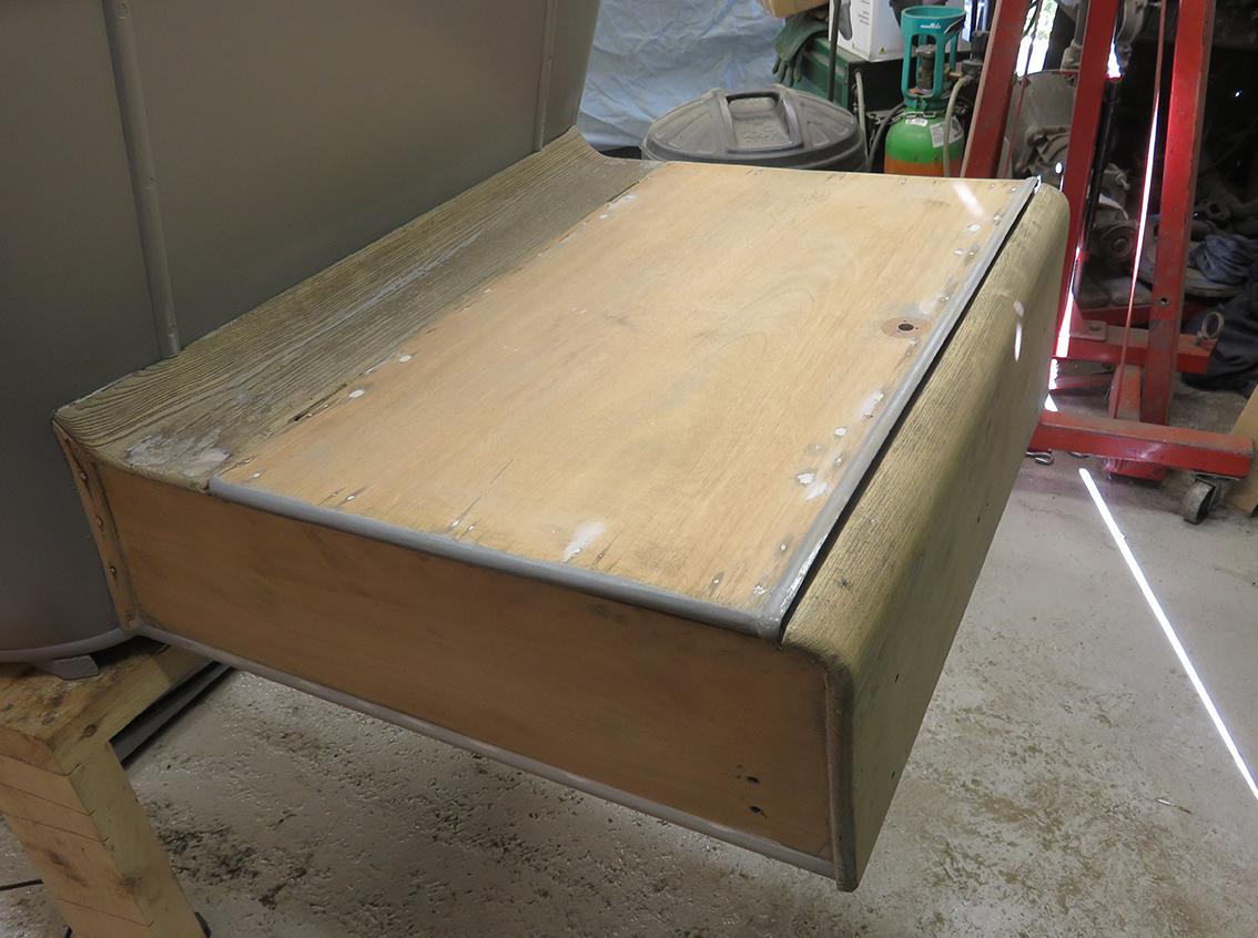
I am starting to confuse myself with photos I have posted and ones that I have not. I have tried to put photos together of the same job and this is the problem. In the future I think I will post the photos with the text in the order I have taken them. The reason for taking photos of different jobs is that while I am waiting for filler to harden I may get on with another job. With the cleaning parts in the blast cabinet my Hydrovane compressor is only just man enough to run the media blasting torch for about 10 minutes before the pressure drops to the point that it takes double the time to remove the paint and rust. Therefore, while I wait for the pressure to build up I do a bit of rubbing down of the body filler. At least it keeps me moving about and not getting bored with doing just one job! Pleased to find how easy wood is to rub down when compared to paint! The two holes on the side were for oil lamp brackets that are not with the car anymore. I found the original holes for the rear acetylene gas lamp. Perhaps the car originally had oil lamps and then early in it's life before 1926 when it was taken off the road it was fitted with 'modern' gas lamps? We shall never know. I will need to get Robert to help me make a new tongue and grooved floorboard for the boot. I have half the missing panel, it has the groove in just one end, at the front, this is so that the panel with the body number on in the photo can be lifted out to top up the diff with oil. There is a metal catch to stop the panel with the number on from jumping out. It always amazes me how many tools you need to do a single operation like sanding the wood. I try normally to work tidily and always clear up my 'mess' when I have finished working, or if I am completely knackered, clear up before I start working the next day. Started filling the screw holes in the beading that is around the panel edges and moulding that is covering the pins that hold the metal to the ash framing. This shows the panel that is missing and the new plywood panel I made up to screw to the area behind the seat back where the original wood panels had cracked. This vertical bit of ash appears to be the only part of the ash frame that has succumbed to bad woodworm. Another job for Robert! This photo shows the problem better. The coach trimmer will need this area to be sound as he will need to fix the leather and upholstery to here. The right hand brass upright support for the windscreen and the acetylene headlamps. I have taken it out of the blast cabinet to see how it's coming on. I found it interesting that the brass casting is backed with an 1/8" thick strip of steel which is soldered to the brass. I wonder if on the earlier Humberette's the brass casting was prone to snapping and they then decided to brace the casting with steel?


-
My 1910 Mitchell "parts car" project
Mike Macartney replied to JV Puleo's topic in Our Cars & Restoration Projects
I really appreciate all your details that you give and the excellent photos. I have been following your posts closely. Being a new member to this forum I started reading your reports way after the start of your project. I have a mill and a lathe which I use, but not to the same high level of workmanship that you achieve. I have learnt a lot from your reports. Keep up the good work. Mike