


RichBad
-
Posts
731 -
Joined
-
Last visited
-
Days Won
1
Content Type
Forums
Gallery
Events
Posts posted by RichBad
-
-
I got some from Big Flats in the US - http://www.bigflatsrivet.com/ and some from a very helpful forum member based in Oz. Big Flats also do a setting tool that fits an air hammer which makes them much easier.
-
Model, year etc....
There are a few about on the web if you ask Mr Google. Also one here http://forums.aaca.org/topic/303831-starting-problem-for-1920-dodge-brother-touring-convertible/?do=findComment&comment=1691360
Cheers
-
Seems to be quite a common issue, hardly surprising with 90 odd years of abuse. My chassis had them replaced at some stage and they were bolted in. Options are to reattach with new rivets or attach with bolts. If you use bolts they should be hi tensile and a tight fit with the chassis and mount.
cheers
-
Awesome, thanks guys - will give it a try with the trouble and strife's lippy and see how that comes out
")
-
Thanks for your help the other day Bob. Have now set it up following your instructions but not quite there yet.
Pinion bearing pre load took a few goes as when I tightened the 2nd locking nut it would change the preload and make it too tight ( I guess it’s just taking up play in the threads in the main but). All feels good now.
Then set the diff carrier which seemed to go well and lined up centrally. Fitted pinion and adjusted to get roughly aligned with crown wheel. Seemed pretty good and needed a small adjustment on the carrier position and then pinion to find the quiet spot.
Then tried to check the contact pattern. Struggled with this, tried paint/ oil mix, lithium grease etc but couldn’t get a good read. Then tried permanent marker and this seemed to work but couldn’t get s typical pattern - perhaps because my gears are quite worn?
Ive attached a few pics below. Crown wheel runout is ~0.006”, backlash is 0.010-0.012”. I tried moving crown wheel in and pinion out but couldn’t find a nice spot without a lot of noise. The drive contact seems to be mid point but too much towards the toe (I think that means crown needs to go out) but coast contact seems too far up the tooth (~3/4 up the tooth which I think says the pinion needs to come in). I haven’t tried taking the crown out more as I thought this may give too much backlash but not sure how much is too much. If I bring the pinion in it gets noisy quickly.
Drive side at opposite sides of ring.


Coast side at opposite sides of wheel


-
6 hours ago, 72caddy said:
Just noticed the petcock to the left of the carb. Make sure this is open when trying to start.
Perhaps not.... I believe that is the drain for the water jacket:)
-
 1
1
-
-
Butterfly, If you can confirm you have both spark at the spark plugs (when cranking) and fuel at the carb we can the help you with other things to try (such as carb and ignition settings). But it’s important to check those two fundamentals first otherwise you could be on a wild goose chase trying all sorts of things which won’t do anything if you don’t have fuel and spark.
-
Here’s a wiring diagram but not sure what year yours is, this is for a 1924.

-
Shouldn’t need a ground to the engine as it will ground through the mounts.
Looking at at your photos it looks like the autovac is missing (supplies fuel to the carb) as there is a disconnected tube. Perhaps it’s been bypassed with a modern pump?
Its likely that the issue is either lack of fuel or lack of spark.
have you checked for spark? If not, remove one of your spark plugs and rest it on top of the engine with the plug lead still connected. Then turn the ignition on and have someone crank the engine to see if there is a spark at the plug.
if not, that’s likely your issue. The wiring for the ignition circuit is pretty simple. Power goes from battery, to the ignition switch then to the coil. The other connection from the coil goes to the distributor (points). Check power to the coil (with a multimeter or test light). Then check wire from coil to distributor/points. Check points are clean. If that’s all good and still no spark it’s most likely the coil or the condenser in the distributor.
If you’ve got spark but still not starting then check fuel supply. If the plugs aren’t wet after cranking then check the carb. There should be fuel in the float bowl (cover can be removed easily with two screws). If there is no fuel in the float bowl then there is likely a fuel supply problem.
-
Bob will know the differences for sure. I know the series 128/129 are different from the earlier ones (e.g addition of handbrake and torque tube etc) but insides are probably mostly the same.
The pinion/crown wheel will also vary between models to account for wheel size etc.
i made my own gaskets, cork for the rear and thin gasket paper for the front. Used the rear cover as a template as the size and hole spacing is the same front and back.
Thanks!
-
Ok, thanks Bob. I’ll get the pinion and diff assemblies put together and assemble them loosely to the housing then give you a call, perhaps at the end of the week.
hoping to start the chassis on the weekend as it’s supposed to cool down - I think we’ve been having some of your weather down here recently!
cheers!
-
Thanks Bob, I remember that now. I didn’t want to trouble you with copying parts of your manual as you’ve got so much on. Is there anything else from the manuals that would help other than what you already told me? Going from what you said the following is what I noted (but may have got muddled on a few steps):
1. Assemble pinion assembly with light Pre-load on bearings (take out play and 1/2 turn more).
2. Fit diff assembly and set bearing to just remove free play (similar to wheel bearing) then approximately align gears.
3. Using blue (or thinned paint) on 1/3 of the gear adjust diff position and pinion to get correct alignment.
4. Adjust pinion assembly in/out to quietest position.
5. Fit half shafts and set with .005-.010” end play using shins on one side.
cheers
-
Hi,
does anyone one have a copy of the rear diff rebuild details from a maintenance manual they could share?
I’m about to start putting mine back together with new bearings and seals after a clean and paint and have some good tips from Bob B but wanted to have the instructions too.
Thanks!

-
Water pump done. Drain tap broke but there were a few threads left so hopefully enough to keep it there.


-
 2
2
-
-
On 18/12/2017 at 9:20 PM, sligermachine said:
I like this it holds up my sail boat can't get on land to big so this is proven good for me --kyle when yor thrugh with your doge or when you have time i would like to part # of the bearings u put in your stearing box im going to copy what u did on my Doge 1929 :]
![20171217_235010_Film1[1].jpg](//content.invisioncic.com/r277599/monthly_2017_12/5a379522ae2df_20171217_235010_Film11.thumb.jpg.95f35b1263545e81d9a0d87cb7b14af6.jpg)
![20171217_235030_Film1[1].jpg](//content.invisioncic.com/r277599/monthly_2017_12/5a379577070d9_20171217_235030_Film11.thumb.jpg.b0deb8ff443406c7cdb15022325583c7.jpg)
Hi, I added details of the bearing part numbers to my post here
-
Thanks - any particular sanding sealer?
-
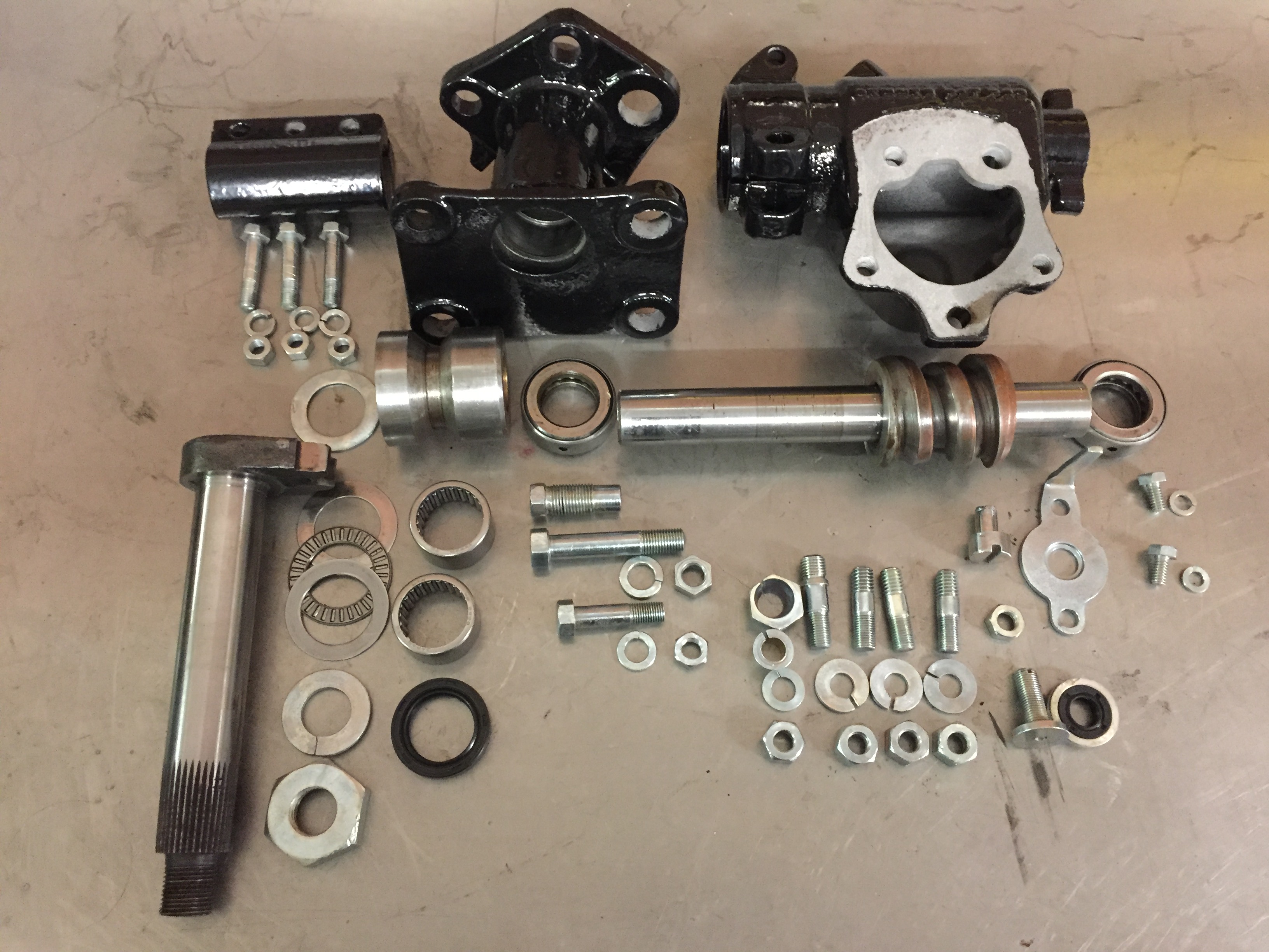
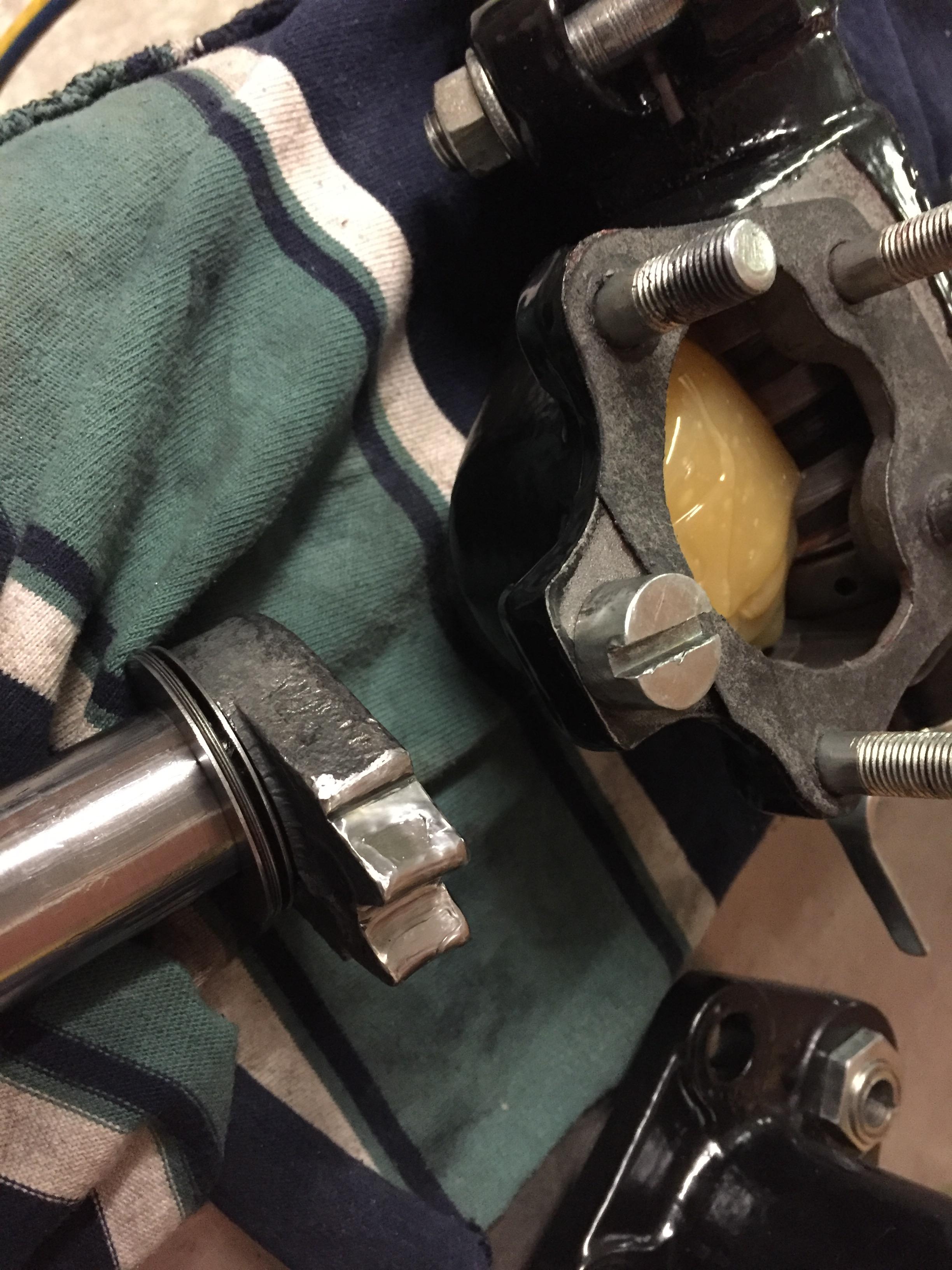
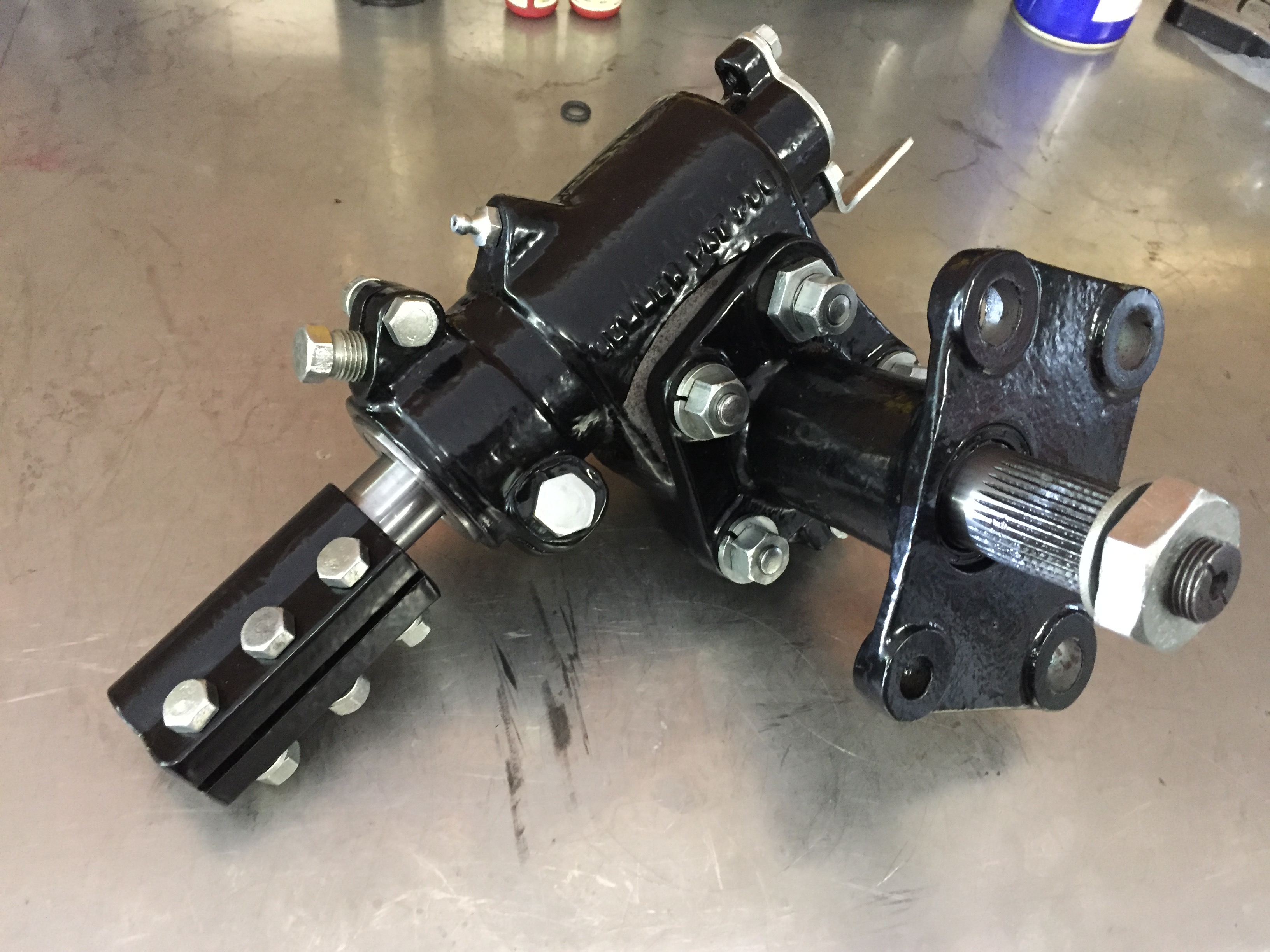
Steering box. Modified with roller bearings on the sector shaft and modern oil seals on the input, sector shaft lower end. Cleaned up the sector shaft teeth to remove play and provide even contact - took about 10 hours of grinding, polishing assembly and disassembly to get it just right. Filled with semi fluid grease.


-
1
-
-
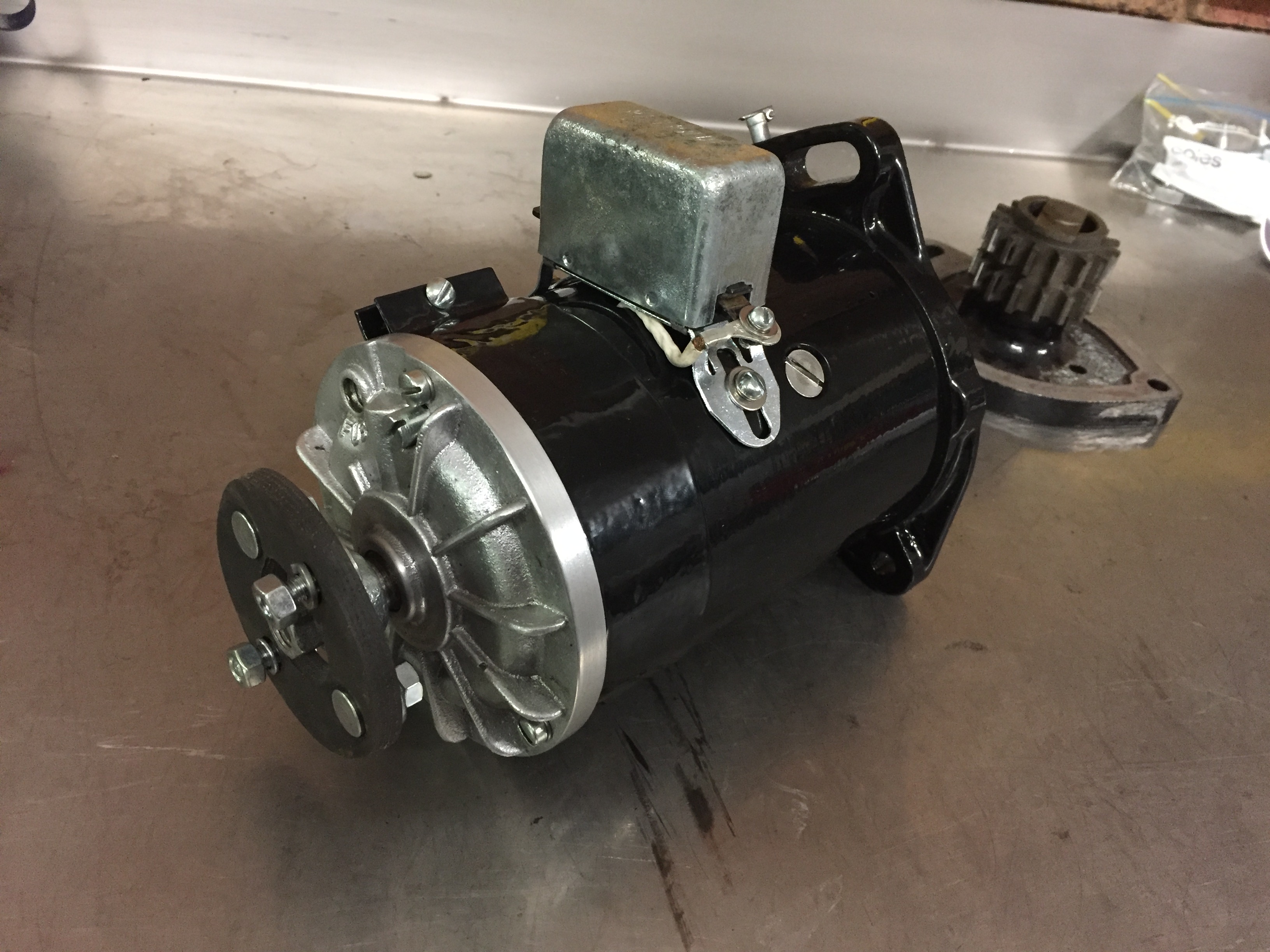
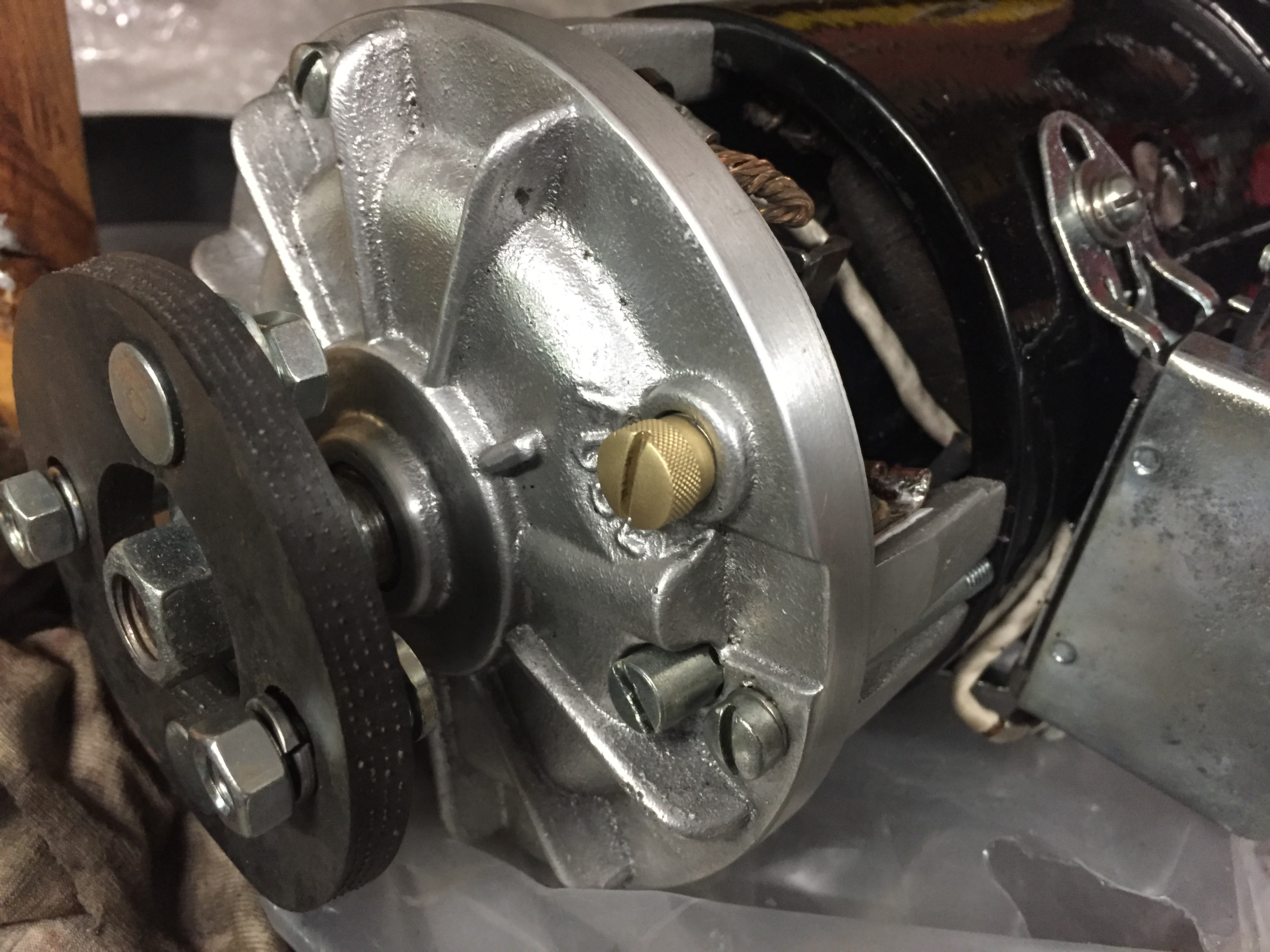
Generator/dynamo done, just needs the fuse holder and replacement nameplate ( original was a bit of a mess).


Got a fuseholder - pic below if anyone was wondering what it looks like


-
I thought a loose nut behind the wheel was a pre-requisite for Dodges
Sorry - Dad joke!
-
Hi,
Can anyone recommend the best option for finishing wooden spoked wheels? I’ve completely stripped my wheels and powder coated the hubs and rims. I wanted to finish the spokes in their natural colour and want something that is tough and will last! Something that can fill the grain would be ideal as a few of the grains have ‘opened’ slightly.
Looking around the web there seem to be recommendations for and against almost everything therefore I’m looking for what people have tried and tested (with good results)!
thanks!
-
Modern seals for the rear diff with machined adaptors to fit them to the existing felt retainers.


-
1
-
-
5 minutes ago, R.White said:
What year is your car? That sump looks a bit later than my' 26. You also have the benefit of a drain hole.
Well done for doing it properly; most of us just settle for a paint job!
Ray.
Thanks! 1927 series 129. Not having a drain hole sounds like fun!
-
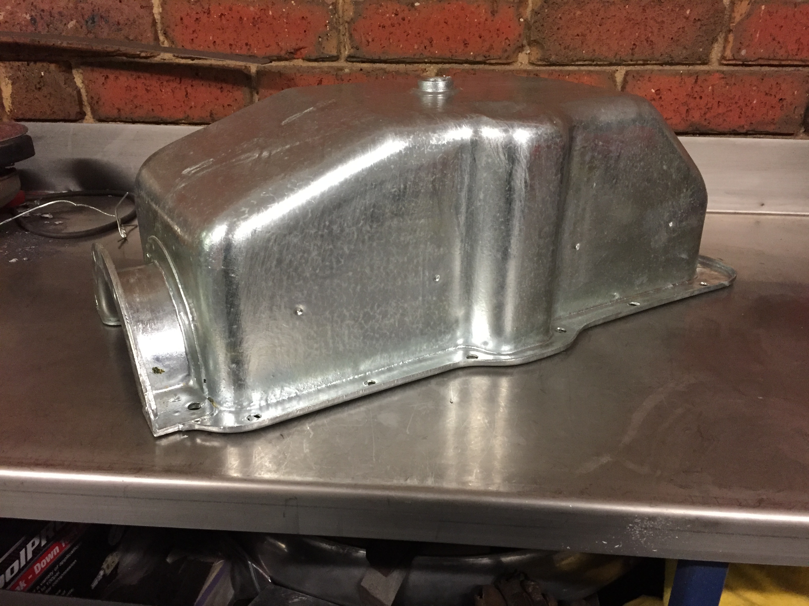
OK, I decided to go for it and get my sump hot dip Galvanized and it came up pretty good
and was easier than I thought it would be.
I first removed the inner oil tray that was riveted in as it wasn’t plated originally and I didn’t want it to distort (also needed it out to clean out the sludge).
The front flange, rear flange/inserts, the rear drain pipe and drain plug insert were all soldered however, after removing all the solder only the rear drain tube could be removed. The drain plug insert was swaged in (after galvanising) with solder to seal. The front flange looks like it was spot welded (probably before plating) with the solder to seal/fill the gaps. The rear flanges looked like they were also spot welded but possibly after the plating (as they didn’t look like they were plated originally). I was planning on re-sealing the flanges with solder but the galvanising seems to have filled/sealed the joints very well.
front flange


rear flange/insert


-
Sump
back from Galvanisers, came up pretty good. Had to remove the inner oil tray and drain tube from the rear (they were not plated originally) otherwise it was easier than expected!


-
1
-


![20171217_235010_Film1[1].jpg](http://content.invisioncic.com/r277599/monthly_2017_12/5a379521a51ef_20171217_235010_Film11.jpg.1f452169871b376642ece0df5c87e172.jpg)
![20171217_235030_Film1[1].jpg](http://content.invisioncic.com/r277599/monthly_2017_12/5a379575a2885_20171217_235030_Film11.jpg.9d4d6d6834bcd30a8b5ee55f05f2b548.jpg)


1927/1928 rear axle/diff rebuild
in Dodge & Dodge Brothers
Posted
Tried with some blue today (may try Wife’s lipstick on the weekend) and got a better showing. Still not a typical pattern but definitely shows more. Seems to suggest pinion position is ok but need to move the ring gear out. Currently had 0.010-0.012 backlash - is it ok to increase this to get better tooth pattern?
Drive side
Coast side
Transfer of blue from pinion to ring