


147 Franklin Airman
-
Posts
155 -
Joined
-
Last visited
Content Type
Forums
Gallery
Events
Posts posted by 147 Franklin Airman
-
-
On 12/23/2020 at 9:46 PM, Rooster said:
When I need to remove the timing gear on my 1929 I find it easier to pull the complete camshaft and gear out. It does mean taking off rocker shaft and pushrods / cam followers. Then it's easy to press the gear off and press new one on. It takes "maybe" a bit longer and might have to cut a new gasket. But I don't know if the 1934 engine has a similar setup.
Can you tell me what held the camshaft in place?
-
Thanks Hugh. I should have stated that the blob of tape below the 17 deg mark was the point that the valve started to open. I moved the fly wheel just to show its position in relation to the 17 deg mark.
I will be stripping the car down shortly & will get report my findings. (after I have confirmed that the piston is at the top in relation to the TDC mark on the fly wheel)
-
On 9/22/2021 at 5:34 AM, Hubert_25-25 said:
If you installed another carburetor, and the vacuum reading was unchanged, then I would rule out the carburetor. The venturi air block looks like it was replaced though it is oddly copper colored. The off centered venturi hole is not ideal but I do not know the real effect of that. Next time the carb is off and the float is removed, put a light behind it. You should see an even air valve tail gap against the venturi block. Then no light between the air valve and the body bore (photo below).
I do not think the probability of a slipped timing gear is very high. The original timing gears had steel center hubs with fiber teeth. The replacements are all fiber. I have not heard of keyway failures with the newer camshaft gears. Below is a description on how to check the valve timing. The inlet valve on 1 or 6 should be just beginning to open before TDC (Top Dead Center)(the 1-6 line). This is about the width of a flywheel tooth or less.
Remove the valve cover or the side cover. From the 1925 Buick shop manual (with some paraphrasing).
"The point at which the inlet valve begins to open can be accurately determined by inserting a piece of letter paper between the valve rocker and the valve stem. Move the paper in the gap. " Roll the engine by hand. "As soon as the paper can no longer be freely moved, the valve is beginning to open."
So the inlet valve begins to open just miliseconds (the width of a flywheel tooth) before the engine rotates to TDC. On the flywheel picture, Below the 1-6 TDC mark in the window is before TDC. Above the 1-6 line is after TDC.
Notice in the last engineering drawing, the inlet valve opens when the piston is 2 thousandths of an inch before TDC.
Hugh


I think I have found my problem. The piece of tape in the photo is the position where No 1 inlet valve opens
 .
.
Why it is so far out is something I need to find out. I also wonder how the engine has ever run like this.
-
6 hours ago, Hubert_25-25 said:
If you installed another carburetor, and the vacuum reading was unchanged, then I would rule out the carburetor. The venturi air block looks like it was replaced though it is oddly copper colored. The off centered venturi hole is not ideal but I do not know the real effect of that. Next time the carb is off and the float is removed, put a light behind it. You should see an even air valve tail gap against the venturi block. Then no light between the air valve and the body bore (photo below).
I do not think the probability of a slipped timing gear is very high. The original timing gears had steel center hubs with fiber teeth. The replacements are all fiber. I have not heard of keyway failures with the newer camshaft gears. Below is a description on how to check the valve timing. The inlet valve on 1 or 6 should be just beginning to open before TDC (Top Dead Center)(the 1-6 line). This is about the width of a flywheel tooth or less.
Remove the valve cover or the side cover. From the 1925 Buick shop manual (with some paraphrasing).
"The point at which the inlet valve begins to open can be accurately determined by inserting a piece of letter paper between the valve rocker and the valve stem. Move the paper in the gap. " Roll the engine by hand. "As soon as the paper can no longer be freely moved, the valve is beginning to open."
So the inlet valve begins to open just miliseconds (the width of a flywheel tooth) before the engine rotates to TDC. On the flywheel picture, Below the 1-6 TDC mark in the window is before TDC. Above the 1-6 line is after TDC.
Notice in the last engineering drawing, the inlet valve opens when the piston is 2 thousandths of an inch before TDC.
Hugh
Many thanks for this information Hugh. It gives me something concrete to work on as the problem is driving me made having spent a lot of money trying to resolve it.
I will have to try a locate a workshop manual somewhere as the one I have is not as detailed as the one you have.
-
 1
1
-
-
Hi Hubert
Thanks for your detailed explanation.
My model 29-25 doesn't have a vacuum fed fuel supply, it has a fuel pump.
Apart from skimming the block & head, reseating the valves, I have tried using a down draft single barrel Rochester carburetor that had been calibrated with the same result. Done a smoke test looking for inlet leaks. Blocked the inlet for the vacuum wipers.
Has the fibre cam gear ever been known to slip on the cam shaft?
My idle jet is a little off centre in the venturi.

-
On 9/19/2021 at 3:58 PM, Hubert_25-25 said:
I would like to know your vacuum gauge reading (mentioned earlier but I have not seen a number). It should be a pretty steady needle between 18 and 19 inches Hg at idle. On my car, I also had some fine rust particles in the hollow bolt that is the air valve adjuster. This was preventing the air valve from moving easily.
Start with diagnostics. Buy or borrow these tools if you do not have them.
1) vacuum gauge reading
2) Check the point gap with a dwell meter or feeler gauge.
3) check the timing at idle with a timing light
4) pull all the plugs and do a compression test of each cylinder
Make a test of the carburetor the last item after verification that the first 4 items are known.
That's interesting. I can only get 15 "Hg which indicates late timing on my gauge but unable to get it any higher. Been living with this for a long time now & have to run with the choke out.
-
On 7/28/2010 at 6:34 PM, sndtubes said:
Quick update:
I squirted WD40 all around the intake while the car was running. No change in engine speed, so I dont' think the problem is a vacuum leak at the intake gaskets
I put my hand over the heat tube inlet. I could feel no vacuum there, so I dont' think the heat tube is leaking
I can put my hand on carb air intake while running. The car immediately dies. So, I'm not so sure there is a vacuum leak. I'm going to try to find a vacuum gauge and check the vacuum at the wiper inlet port. At present that port is closed off with a small hose (not leaking)
I'm becoming suspect of the air valve. I'm wondering if it is working properly. When the carb was rebuilt a few years ago, the spring was replaced with the correct one.
More updates soon. Thanks for all of the great suggestions.
Have you been able to resolve your issue with the popping thru the carb. I would be very interested to hear.
-
52 minutes ago, jps said:
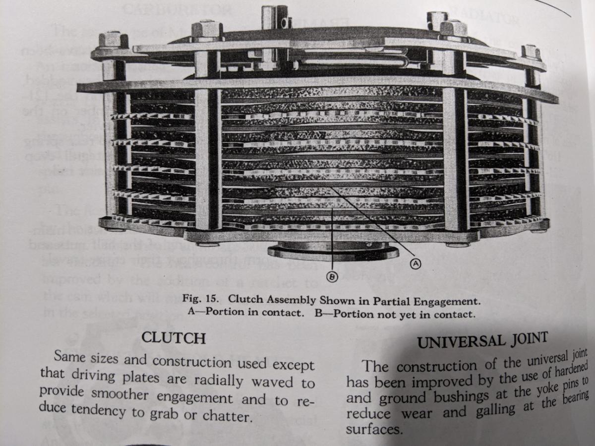
OK, finally I found something that answers the question clearly, and I was wrong. The driving plates are NOT flat and they DO have a wave to them - described here and shown pretty clearly in the photo below (notice the non-uniform gap between the driving and driven plates, and the text below the photo) from the 1929 Buick Detailed Specs book, page 12:
John
That's a lovely clear picture & a description that I've been looking for. Thank you. It goes against a lot of theory but obviously this is my problem. Now I have to decide how much of a bend to put in the plates
-
1
-
-
Thanks John, very interesting read of the old post.
"
the outer edges to have a "wave" pattern.
"
I still cannot visualise the wave
-
57 minutes ago, Oldtech said:
I agree with John, The discs should be flat, if there is any appreciable wave to them they won't release. Multiple disc clutches drag anyway. Check the grooves in the flywheel for nicking as that makes the discs hang up. Careful attention with a die grinder will help .
Just as a point of interest, the reason I replaced both the driven discs & the driving discs is that the clutch was grabbing before & the ones I took out were worn.
-
13 hours ago, jps said:
I think that "radial wave" simply refers to the "lobes" or "teeth" that exist on the periphery of each disc plate. They are called "radial" because they are like rays originating from the center of each plate every few degrees. However, the disc plate facings themselves are flat, as it says here in the manual:

The "wave" exists only at the edge where each of these spaced rays end - sort of like on a U.S. quarter coin that has small ridges on the edge - and not on the facings themselves.
John
I agree in that the "unlined discs" should be flat, it's the lined discs that look "waved" in the photo which is causing me to question this.
-
3 minutes ago, tonybuick said:
could the splines be worn making the plates unable to slide in or out easily causing the plates to hang up so it isnt a smooth action a bit on or off when working the clutch pedal
I never thought about that. The driven discs are brand new. I would need to check the hub splines. Thank you for your input.
-
5 hours ago, 27donb said:
Thank you for the clarification.
I understand what you mean, like a spring wave washer, the plate itself has high and low spots.
Those pages from a 1929 shop manual show what appears to be the same basic clutch as my 27. To me, the plates all look flat, no wave. My 27 clutch has all flat plates as well.
I could be wrong on your application. It just seems that if some of the plates did have high and low spots by design, those spots would overheat and blue due to the concentrated friction on such a small area.
I think all the plates, are flat.
Hence my question, what is a radial wave?
-
9 minutes ago, 27donb said:
I'm confused as to what "radial waves" in a driving disk refers to. Is that term from a manual?
I thought multi disk Buick clutches had driven disks and friction disks. What are radial waves?
If you look at the 2nd picture sent by jps you will see the driving discs that have a radial wave in them. My guess is that they are bent (for sake of words) in order to create a high & low area which would reduce the friction until fully released by the clutch pedal . It's this radial wave that I'm trying to confirm.
-
1
-
-
3 hours ago, Old26Buick said:
Is this clutch like a 27 Standard. I rebuilt mine myself
If its a multi plate then probably yes, did the lining plates have the radial wave in them?
-
56 minutes ago, michealbernal said:
The factory service manual for the Allis Chalmers model M tractor recommends washing both the master and steering clutches by installing a plug in the clutch compartment drain hole and adding kerosene to the compartment. It then recommends driving the tractor while releasing and engaging the clutches for about 10 min. It then recommends draining the compartments. This model tractor was built from the 1930s into the mid 1940s.
Thanks Michael. This is very interesting. Does it say why it would need washing out or what the advantage would be. I will try & search for more info
-
2 hours ago, jps said:
You may already have this info, but if not, here are the 2 pages from the 1929 shop manual on the clutch:
John


Thanks JPS, yes I have the manual. The radial waves are not clearly visible
-
2 hours ago, raydurr said:
About 35 years ago I remember my grandfather describing clutch grab in his 1929 Buick. His solution was to stop up the drain slot in the bell housing and fill the bell housing with " coal oil". He would let sit for a little while , push in and out on the clutch pedal a few times and finally drain the fluid from the bell housing. He said that clutch would be smooth as silk for a year or two afterwards. I have considered doing this myself lately. I am not suggesting this as a remedy, merely passing on a story of what occurred probably 85 years ago. Good luck!
Thank you for this, I was almost thinking about adding a little oil as I remember motorbikes having multi plate clutches & they were always in oil.
-
Can anyone describe or show me what the radial waves in the driving disc look like on the 1929 multi plate clutch?
My clutch is either off or fully on, very difficult to get it to slip.
-
20 hours ago, Hubert_25-25 said:
I do not think the head bolt tightening sequence is correct on that non GM worksheet. It goes against how I have been taught long ago about tightening cylinder heads. This is the correct head bolt sequence from GM for 1926 Buick. The Buick head is an odd bolt layout. It is treated with some bolts that are close together "as pairs" and works it's way in a circular pattern from the middle to the ends. Working evenly from the middle to the ends is how we do it today. That other one is very non conventional and I have never seen anyone tighten bolts down one side starting from the middle. That drawing has made it's rounds. This photo is from the 1926 GM export manual.
Also made an update to the attached thread. This error is likely in many places where people have asked for Buick torque and head tightening sequence. Hugh


Many thanks Hugh, That is the correct picture of my cyl head.
-
2
-
-
31 minutes ago, Rock10 said:
Many thanks Rock10
-
1
-
-
Hi
Does anyone know what the torque setting should be on the cylinder head bolts on a 1929-25 6 cylinder standard engine?
-
3 hours ago, Brooklyn Beer said:
You can trust Jim. 100% stand up guy. Looking at your trans from the perspective of the old days of running hot rod Mopars and street racing I can honestly say yours has shit the bed. May I ask if this just let go under normal driving ?
Hi Brooklyn
All is good with Jim.
I had pulled away going downhill and as soon as I went into 2nd she let go and of course the clutch doesn't do anything as the wheels were still turning the transmission. Not the first time this has happened to me.
-
53 minutes ago, 29 franklin said:
Hello, I have a totally rebuilt warner T3A transmission. I have it as a backup just in case something would happen to my trans in my 1931 151. I am very reluctant to sell but will sell to a club member to get the car back on the road. I can write you a list of what has been done . It has not been in a car since being rebuilt and was done in March of 2018. You can PM me or look me up in the Franklin roster. I do not know how shipping would go .Thank you Jim Bockin
I have sent you an email Jim.


 .
.


Best Way to Remove a Timing Gear - 1934 Series 50
in Buick - Pre War
Posted
Thanks Bob, that sounds really easy. Hope it's the same on my 29