


Model56s
-
Posts
398 -
Joined
-
Last visited
Content Type
Forums
Gallery
Events
Everything posted by Model56s
-

1956 Chevrolet 1/2 Ton Panel Truck
Model56s replied to Model56s's topic in Our Cars & Restoration Projects
OK, I’m officially excited about getting the body and chassis reunited. That is a stunning finish. Tonight I used wedges to get the pinion leveled, about two hours’ work. I have one more troublesome mystery to solve - properly running and securing the brake lines. I’ve approximated the former run, regretting not keeping the chassis and components in one large assembly when I separated the body. Had I done that, I could have easily photo documented the exact brake line runs and securing points. I saved the lines knowing I needed the archive and it was these lines I’m using to map out the new tubing runs. I intend to have that done before the weekend.

-
1956 Chevrolet 1/2 Ton Panel Truck
Model56s replied to Model56s's topic in Our Cars & Restoration Projects
My wife's choice. Although I was leaning toward the factory blue, I'm very happy with Forest Green and Adam's workmanship. Also, a shout out to Allan at MidNite Auto Supply in St. Peters, MO for his assistance in spec'ing and installation of the U joints. Although the drive shaft was mated to this transmission, the rear end is not stock (66 Impala). I bought the U joints a couple weeks ago and installed one on on the shaft (not too difficult with a large C clamp), but had difficulty getting one of the external keeper clips in the groove. I decided to pull the trans yoke and bring everything to Allan yesterday. 20 minutes later and this is no longer a hill to climb. I don't know why the Forum rotates images 90 degrees.

-
1956 Chevrolet 1/2 Ton Panel Truck
Model56s replied to Model56s's topic in Our Cars & Restoration Projects
I’ve been out of town all week, but Adam has been busy. The small interior parts have been painted with a couple body color items to be done yet. The large piece forms part of the overhead above the seat. A previous owner had cut a jagged hole in it to mount a speaker, which Adam filled. When I get back, wedge shims need to be installed on the rear end leaf spring perches to level the pinion shaft, then install the drive shaft and brake lines.
-
1956 Chevrolet 1/2 Ton Panel Truck
Model56s replied to Model56s's topic in Our Cars & Restoration Projects
I’m very happy with this work, the colors and especially the contrast with the ivory top. What fortune to have this craftsman local! The fuel system is pretty much installed with the line run and tank secured in its final position. Next is to install wedges between the rear leaf spring perches and the axle to bring the pinion shaft parallel to the ground, then install the U joints and driveshaft. The brake master cylinder is clean and ready to be installed, then lines will be run. Still a lot to be done - here’s a small sampling: steering, shift rod and linkage, brake hoses, window, windshield and door rubber, maple planks and stainless strips & hardware for the cargo floor, wiring harness, and we haven’t mounted the body and front clip on the frame! Interior paint, seat upholstery, Adam to paint the steering wheel, buffing…new tires…parking brake cables, fill and bleed the brake system. Enough whining for tonight.


- 194 replies
-
- 10
-

-
1956 Chevrolet 1/2 Ton Panel Truck
Model56s replied to Model56s's topic in Our Cars & Restoration Projects
I haven't done much on the chassis in the last week, attending to other things. I bought a 25' coil of 5/16th" nickel/copper alloy tubing for the fuel line to go with the 1/8th" coils of the same alloy I have for the brake lines. This 5/16" diameter will also be used for primary brake fluid supply to junction fittings that feed 1/8" tubing branching to the wheel cylinders. I've practiced flaring the tubing (double for brake, single for fuel), and was going to complete the fuel and brake line runs this weekend, but a large long-dead oak came down during our high winds on Tuesday, and that booked my weekend up for cutting and burning wood. I stopped work with the chain saw at Noon today with 3/4th of the job done on the tree and no stump to remove. The main trunk (30" dia.) and two large branches were rotted and hollow (lots of old, dry honeycombs) so cutting was quick and I don't have to split anything. I'll have it cut up by mid-afternoon tomorrow. We're having a burn party tomorrow night. So, the plan will be to run the fuel and brake lines in the evenings this week since Adam is closing in on completion.


-
1956 Chevrolet 1/2 Ton Panel Truck
Model56s replied to Model56s's topic in Our Cars & Restoration Projects
Looks great Adam! I'm tempted drive out to see it. -
1956 Chevrolet 1/2 Ton Panel Truck
Model56s replied to Model56s's topic in Our Cars & Restoration Projects
68oF today.Inner fender panels and top bracket are painted, lower panel in the picture needs another coat. The "Universal" fuel tank (Tanks, Inc.) is positioned - this was the closest tank I could find that clears the drive shaft, mounts to the side of the frame (fuel filler door is on the passenger side quarter) and provides reasonable ground clearance. I have to mate a 2" 45 degree exhaust pipe section to the short tank filler neck to get the filler opening in the right position on the frame to accept the body-mounted 1 1/2" OD filler tube. I'll need a 2" to 1 1/2" reducer to mate them (Tanks, Inc.), or a 2" filler tube that would mount to the body, and a fuel-safe 2" hose for coupling. The two tank mounting straps need to be 32" long and will be cut from pre-punched 1 1/4" strapping (about 18 gauge) from Lowe's, secured with stainless bolts, fender washers and (nylon) locking nuts to frame and cross members. I have rubber to insulate the tank from rubbing. This tank clears the drive shaft by 3/4", so losing a U Joint could rupture the tank - It can move outboard another inch to contact the frame, but due to the shape of the cross member would lower it another inch and I don't want any less ground clearance. Adam texted me this afternoon that the quarters are "rough worked" and he's starting on the back doors. I still have to finish mounting the tank, cut/bend/flange and run fuel and brake lines, install the parking brake cable (needs some rework) and install drive shaft/U joints. We want to transport the finished body back on the chassis and I don't want to have to lift it off again to get at something later. All for now...

-
1956 Chevrolet 1/2 Ton Panel Truck
Model56s replied to Model56s's topic in Our Cars & Restoration Projects
The engine is installed. Now for some comedy. Notice in a few posts back the 1” difference in overall length between the motor/transmission mounting holes in the cross members and on the engine itself. I had the engine mounting brackets reversed, the right on the left and vice versa. There is no need for extra hardware or fabrication. BTW, For some reason the forum rotates the picture 90 degrees to the right when it’s inserted. We’re all calmed down now.
-
1956 Chevrolet 1/2 Ton Panel Truck
Model56s replied to Model56s's topic in Our Cars & Restoration Projects
So, this is why I held out 7 months for Adam’s schedule opening, this attention to detail. There’s another difference between Adam and me: he’ll look at a panel and say “that’s rough!” and looking at the same panel I’ll say “hey, that’s not too bad!”. But, I’ve never painted a car before. Without my ignorance I may not have taken on this project. No, I would have, I love this truck’s looks and utility. The cargo floor will be maple. More good news - local BCA Chapter president Chet came over today and validated my approach to dealing with the 1” difference in motor/bell housing mount distance and corresponding cross member mounting site distance. That solution is to fabricate new front motor mount brackets with the mounting holes 1” further back. In the second picture below, you can see that the front mount is leaning forward. My source will be Nadler’s welding. They’ve been at that location since 1951. We found out that this front mount approach will work when we bolted the repro radiator in with the fan and upper pulley installed and found 5/8” clearance with the engine in the “forward” posture. I’ll produce the new brackets, finalize the engine installation and turn to the fuel system. Brakes and drive shaft + U Joints to follow. Also, the four 15X7 Smoothie wheels (Wheel Vintiques from Summit Racing) arrived a couple days ago and Adam has them for painting body color, Forest Green, like Steve’s truck. I test fit all 4. Adam is shortening my time window to ready the chassis for the body, which is awesome.


-
1956 Chevrolet 1/2 Ton Panel Truck
Model56s replied to Model56s's topic in Our Cars & Restoration Projects
I began dropping the engine/trans onto the chassis last night and found that the bell housing mounting holes were 3 inches further back from the transmission crossmember mounting holes. I bought two 3x5x1/4” plates today and cut them to adapt the bell housing to what I have. But then I noticed that the front mounts can be attached either to the brackets bolted to the front crossmember, or after looking and measuring for 10 minutes, found that they can be mounted directly to the crossmember in factory holes. Doing this would make up all but an inch of the difference by my measurement. It looks like Chevrolet punched these holes in the front crossmember for trucks with Hydramatic and installed the brackets for those with a manual transmission, like mine. Tomorrow night I’ll remove the front mounts & brackets and reinstall the mounts on the crossmember, then drop the engine in to see if the last inch is due to mis-measurement. If not, I’ll drill the adapter plates accordingly. At just an inch further back, the bell housing mounting holes are directly over the mounting pad, so the pieces I cut off the plates will serve as a spacer for bolt head clearance.

-
1956 Chevrolet 1/2 Ton Panel Truck
Model56s replied to Model56s's topic in Our Cars & Restoration Projects
Hi Mike, you sound like my wife "...haven't you done______yet?🤣 Not yet since I'm learning as I go, and know so little to begin with. Truly - I had to think about this. Tell me what you think of this approach - 1) seal the water pump inlet and the open intake manifold hot water supply brass fitting (circled in the picture), 2) drill a piece of 1/8" steel plate I have to match the the bolt pattern on the thermostat housing lower half face and to accept a metal 2-piece tire valve in the center,(3) assemble & bolt it on the housing face with a gasket and RTV. Once that cures, pressurize via the tire valve & check the pressure with a tire gauge, then check again in 6 hours to verify no drop. If it loses pressure, first soap test the fitting & inlet hose seals, and exposed freeze plugs. If they're good, the bell housing has to come off. If that's the case, maybe the truck becomes a static display item. I got the chassis into the other bay and that's about it for the weekend. Three of my children came over and ambition evaporated with each passing minute of their visit. Thanks again for the suggestion to pressure test the cooling system - I would have never thought to do it.
-
1956 Chevrolet 1/2 Ton Panel Truck
Model56s replied to Model56s's topic in Our Cars & Restoration Projects
Adam got the exterior primed and ready for finishing body work. We will use base coat/clear coat based on Rooney's experience - thank you again Steve for your valuable information regarding correct paint and placement! Tomorrow I have to transfer the chassis off the 4 post lift and into an open bay to give the shop crane access for dropping the engine/transmission assembly in the proper spot on the chassis. To do this, I have to contend with an iced-over fairly steep driveway (5' of drop to the street over a 50' run). I'll spread salt before my morning coffee and wait an hour for it to do its thing.
-
1949 Buick Super Restoration project
Model56s replied to Skvitt's topic in Our Cars & Restoration Projects
Very satisfying, and I agree, great work. -
1956 Chevrolet 1/2 Ton Panel Truck
Model56s replied to Model56s's topic in Our Cars & Restoration Projects
The paint store did not have the PPG number for Forest Green, so I'll ask Rooney for any reference numbers he used for his truck. They did have the interior color and we should have a pint sample tomorrow. Meanwhile, the interior is primed. Adam keeps moving.
-
1956 Chevrolet 1/2 Ton Panel Truck
Model56s replied to Model56s's topic in Our Cars & Restoration Projects
Hi Steve, and thanks for the comment! Adam has been sanding, getting ready for primer and we’re working on the right tone for the colors. The paint store had an issue locating the proper color so I’m going to meet Adam there and get this ID’d. I mentioned this to my wife who is now favoring a lighter shade and she perked up - “oh really?!” so maybe we can accommodate this. I liked the lighter shade almost as much and showed her Rooney’s beautiful specimen, which she liked. We’ll see, it’s fun knowing you can decide on anything you want. This won’t happen, but Volkswagen has a beautiful orange that would look great on the truck. I have the motor mounts assembled and ready to install on the frame, and need to get two large bolts for the bell housing mounting points, then the engine meets the chassis. I have to get the chassis off the lift and into the next bay. I’m also prepping for paint the single rear light fixture that’s mounted on the left cargo door. I can find the replacement lens, but not the bezel or door interface gasket.


-
1956 Chevrolet 1/2 Ton Panel Truck
Model56s replied to Model56s's topic in Our Cars & Restoration Projects
Mike, great suggestion that did not come to mind! I will do so. -
1956 Chevrolet 1/2 Ton Panel Truck
Model56s replied to Model56s's topic in Our Cars & Restoration Projects
Adam got the cargo doors aligned today. One of the next steps is to look at the exterior and interior colors on a piece or metal in the sunlight.
-
1956 Chevrolet 1/2 Ton Panel Truck
Model56s replied to Model56s's topic in Our Cars & Restoration Projects
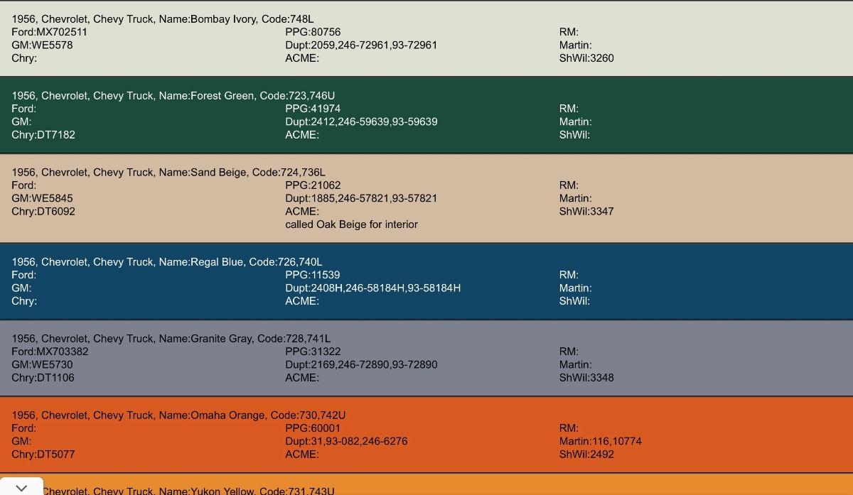
Hursst, so true. Not to sound like Barbara Walters, but the path of my personal growth is littered with these little thumb tacks and I go barefoot. Rooney, thanks for posting this picture! Between computer screens and indoor lighting, you never know how it will look. Gorgeous truck! How long have you owned it? Did you restore it? My wife was looking at a picture of an early 50s Advance Design and liked the lighter green, but the train left the station. We could not find the data plate color code 234G anywhere; 1956 truck colors are 700 series like yours so it makes me wonder It was in the mid-60s and sunny so I worked with the garage door open. The freeze plug is in, the bell housing adapter is on, the torus was sealed and bolted up with a new gasket and RTV and all bolted together. I had to take a 2” Shallow freeze plug and cut 1mm from the flange all around. I coated the sealing surface with RTV and tapped it in and the plug was flush. A good hammer rap in the center and it sealed up tight, then more RTV around the seam. The adapter has a circular face cast and machined that corresponds to the freeze plug, so where that face contacts the block/plug got an even coat of RTV. As I told Adam earlier, if either plugs on the back of the block leak, the engine has to come out. I decided to use new Grade 5 bolts on the bell housing. The new motor mount bolt is shorter that the original, so we’ll see how it sits when I drop in the engine this week.


-
1956 Chevrolet 1/2 Ton Panel Truck
Model56s replied to Model56s's topic in Our Cars & Restoration Projects
No pictures tonight because no progress on what has consumed me for two days. Two days. I’m having an issue replacing the upper freeze plug on the back of the block. There are two, one in the center just below the deck and one below right near the starter. The upper one is covered by the cast factory bell housing adapter required to mate the 235 six to the Hydramatic. The factory designed and cast a recess in the adapter to accommodate the upper freeze plug, but the steel plug must be flush with the back of the block. Further complicating this is that the plug’s convex side must face outward so it can be sealed in the opening by a (ball peen) hammer strike in the center which forces the flanges even more against the walls of the machined opening. As an extra measure, I will coat the machined sides of the block opening and the adapter machined face with RTV - if this thing leaks, the tranny must be separated to deal with it. I’ve gone through 3 freeze plugs trying to get this right. They are 2” Shallow, but still require the edges of the sides to be ground down in order for the crown to be flush with the block when the edges “bottom” in the block against the terminus of the machined surface. I would grind them down to the calculated depth & drive them in, only to see a 1mm protrusion 😡. I’m on my fourth freeze plug (I’m getting good at chiseling a slit and prying it out) but this time I know precisely how much to grind off. It cannot be driven in the other way since there is no way to expand and seal. I hope you’re following me on this. Once I get this right, the Hydramatic and engine can be mated and installed on the chassis and I can move on to U Joints, fuel and brake systems and be ready with a running drive train for the body drop and get it on the road. We’ll, there’s wiring and a bunch of other smaller things, what they call in the Telecommunications industry “the last mile”. OK, I’m done venting. -
1956 Chevrolet 1/2 Ton Panel Truck
Model56s replied to Model56s's topic in Our Cars & Restoration Projects
This attention to detail, especially concerning paint, is why I was willing to wait 7 months for an opening in Adam’s schedule. There was a fit issue with the instrument cluster in the Dynacorn repro dash, but fortunately it was relatively minor. Adam began to tackle the dash in the morning and by the afternoon it was in.
-
1956 Chevrolet 1/2 Ton Panel Truck
Model56s replied to Model56s's topic in Our Cars & Restoration Projects
Adam has made some progress - the front doors are aligned and the old dash is out without being butchered, seen in the background. Aligning the doors now helps avoid paint chipping during reassembly and regular use. He’s also made progress on the few dents in the roof and the top of the wheel wells which are exposed in the interior of the truck, and very visible. He would have had the two rear doors done, except I forgot to bring those hinges which are safely stored in my basement. He’ll have these and a couple other parts tomorrow morning. He has a YouTube channel, Antique Automobile Service, so check out his workmanship and projects. Chet, the Gateway Buick Club president loaned me his engine lifting bar and chains this afternoon to get the 235 six off the engine stand. His knowledge is backed by more years of experience than he’d probably admit. The engine will be mated to the Hydramatic tomorrow when I get back from Adam’s shop. I’m beginning to pull parts together that we’ll need in the coming weeks, especially interior parts that will need to be painted the same beige color as the rest of the interior. I chose 1956 color Forest Green in single stage urethane for the exterior color (solid, not metallic).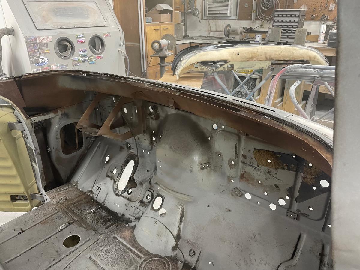


-
1956 Chevrolet 1/2 Ton Panel Truck
Model56s replied to Model56s's topic in Our Cars & Restoration Projects
I completed the refresh of the Hydramatic tonight and set it on a furniture dolly. Keith Hardy’s Old Online Chevy Manuals was indispensable. The side cover gasket came right off. The next step is to get the engine off the stand, bolt on the Hydramatic bell housing adapter and flywheel to the crankshaft, then bolt the engine to the torus and to the Hydramatic. Yeah, piece of cake.😳 That’s going to be involved because the flywheel forms the torus half on the engine side - imagine the modern flex plate forming half of the torque converter. You have to line up these two high-mass objects in order to assemble the torus. I’ll position the engine as the stationary member and maneuver the Hydramatic with the shop crane to line it up, kind of like mid-air refueling. Since I have the new motor mounts and the transmission mounting pads are good, the engine/transmission assembly should be on the chassis this weekend. I dropped off the new dash and the grill surrounds at Adam’s and found that he has already started on the body. I’ve also attached a picture of the pristine data plate the sand blaster took care not to harm. If the rivets weren’t so old, I would have thought it was a repro.


-
1956 Chevrolet 1/2 Ton Panel Truck
Model56s replied to Model56s's topic in Our Cars & Restoration Projects
Indeed. We see very little metal fabrication required. The front floor just below the toe board on both sides has lots of perforations which will be treated with fiberglass. The rear floor sill is also perforated on the passenger side, which will get metal reinforcement. That was caused by the plywood cargo floor there retaining moisture, so I’ll seal it before laying the new floor. -
1956 Chevrolet 1/2 Ton Panel Truck
Model56s replied to Model56s's topic in Our Cars & Restoration Projects
An unexpected challenge was how the caster bearing races filled with media from the blasting and would not rotate! The guy on the floor did the blasting and is seen here working the casters to free them up. Adam will have to blast them with a nozzle to clear them. We had rain a few days ago and nearly all of the snow is melted, so the roads were dry. It was sunny and 65 - perfect for transporting a bare metal truck to surgery. It turns out that the front fenders are 1956 vintage, almost certainly original, with patch panels in the lower rear wheel arch as to be expected. Chevrolet moved the elongated fender emblem above the belt line and sure enough, four mounting holes in the correct position were welded shut.


-
1956 Chevrolet 1/2 Ton Panel Truck
Model56s replied to Model56s's topic in Our Cars & Restoration Projects
Adam and I picked up the body shell & panels from the blaster this afternoon. I’ll make a couple posts tonight. As posted earlier, besides the roof the media blasting revealed filler in the lower sections of the quarters, on both sides from the door back. With the filler removed, we found good patch panels done long ago, before 1985. Rather than finish the patch panels by completing the welding, grinding, then applying a skim coat - whoever it was just tacked the panel on with some stitch welds, did some grinding and applied lots of body filler. This was good to find as Adam just has to finish it correctly. The driver side looked the same. A dent in the passenger door (blasting reveals the history!) was treated the old school way: drill holes, screw in a slide hammer and apply equal parts measured force and patience. Again, they just skimmed filler over the holes. The door work was remarkable in that there is no access from the inside and the metal was smooth. I don’t have a picture of an 8” line of holes running vertically about an inch from the front edge, starting 10” from the door bottom. Again, the metal was smooth and yet no access from the other side. Whoever this was had talent. Today, a brass rod is welded to the dent and pulled, then cut off and finished off. Given all of this, the truck’s condition was as advertised - I hold the seller in high regard.


