


rustranch
-
Posts
38 -
Joined
-
Last visited
Content Type
Forums
Gallery
Events
Everything posted by rustranch
-
1909 Brush Model BC followed me home last week.
rustranch replied to rustranch's topic in Brush Automobiles
Progress update. I’m about 75% on my “Get her running” time line. I’m about 50% finished on the running gear. Being gone for a month on Summer holiday has crimped my timeline. Next Mount hood former to firewall. Brakes and linkage to pedal. Then on to the long list of little things. Install gas and oil tanks, dash oil sight glass and lines. Install throttle and timing levers and connections. Upper and lower radiator hoses. Install Ignition box and buzz coil. Build a battery bank under seat. On and on and on.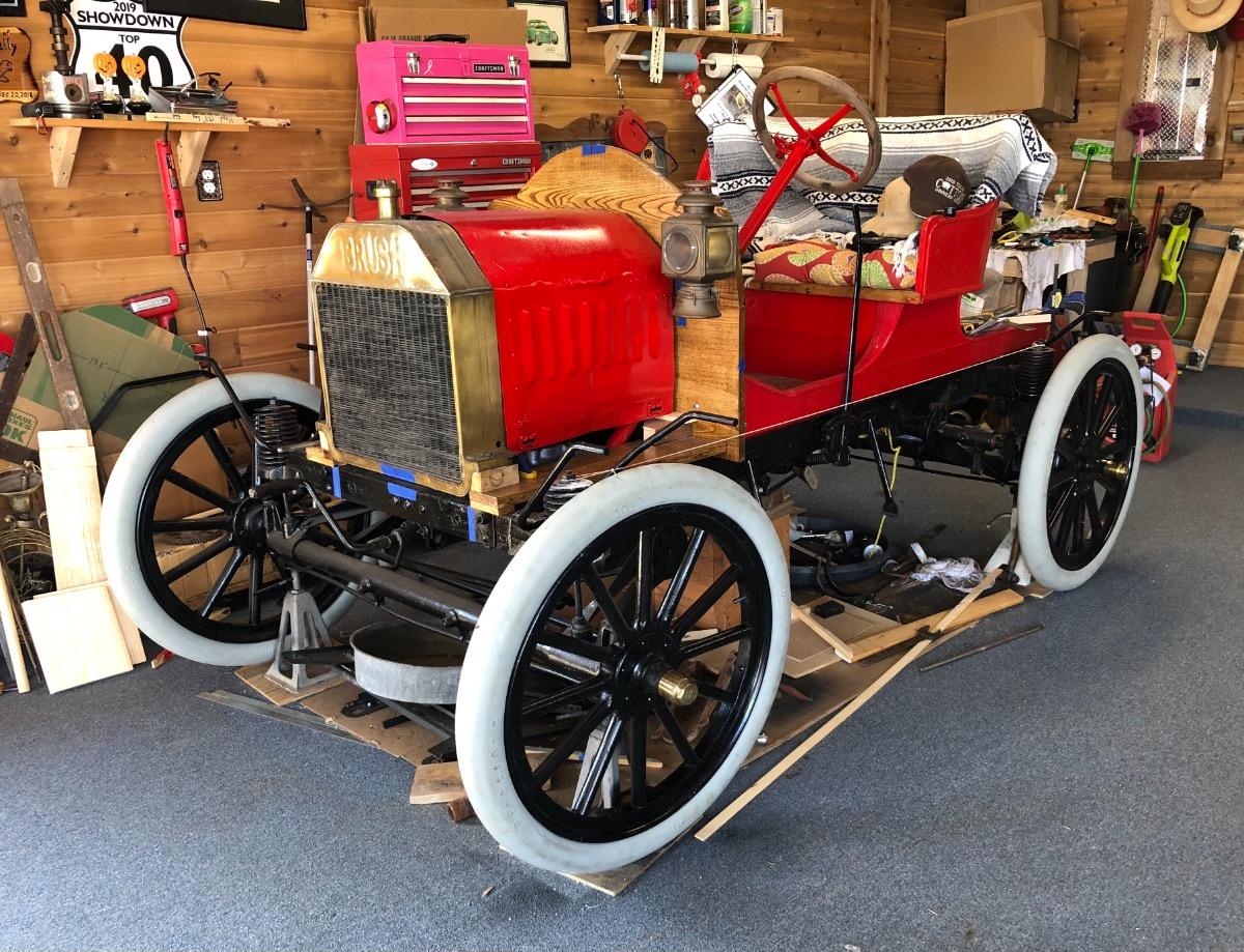
-
1909 Brush Model BC followed me home last week.
rustranch replied to rustranch's topic in Brush Automobiles
Project update. I put together a temporary ignition system using a spare coil from my Model T Ford parts collection. Also I borrowed the battery out of my 1915 Model T. A couple of squirts of starter fluid in the intake and I cranked away. Bam it starts, with a chug, chug, whizz, cough, sputter, chug, chug chug. It runs. My project timeline had me attempting to start the motor this week. So I’m kinda on track. Although truthfully I’m behind on the running gear. I will say this is a major milestone on this project, I’m very excited. Listening to the sound of the motor is intoxicating. Now to work on lots of other part. Best guess the last time the motor ran was 70+ years ago. My son thinks 100 years is a better estimate.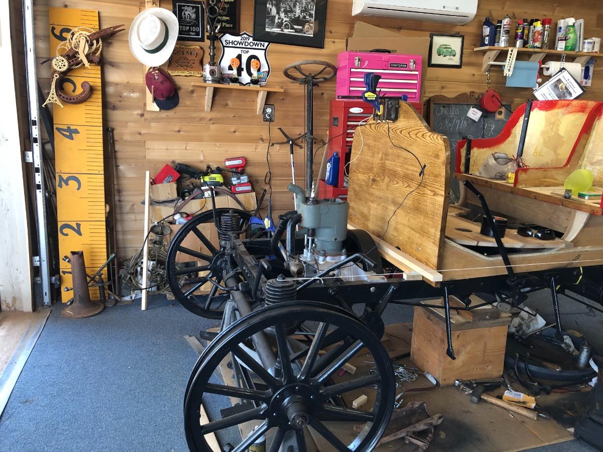
-
1909 Brush Model BC followed me home last week.
rustranch replied to rustranch's topic in Brush Automobiles


-
1909 Brush Model BC followed me home last week.
rustranch replied to rustranch's topic in Brush Automobiles
Look what I found in a very small car museum in DeLeon Texas population 2,246. There are around 10 or so very unique autos, all lovingly restored to mint driving condition. In the very back corner this little gem was labeled as a 1909 Brush Runabout. From extra blocks added to the frame on all four corners it makes me think it was a southern wide track model similar to what Ford offered with the Model T’s.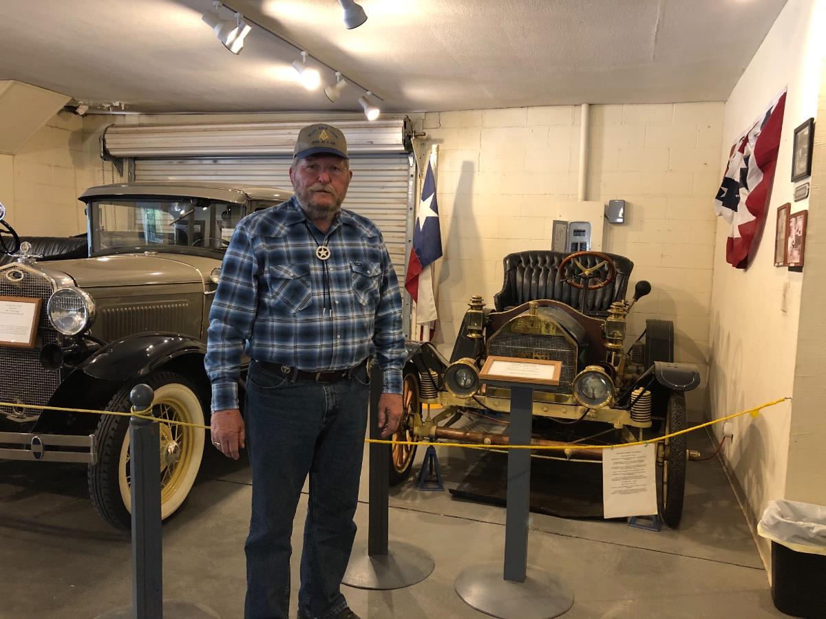

-
1909 Brush Model BC followed me home last week.
rustranch replied to rustranch's topic in Brush Automobiles
I finished fitting the rod to the crank and installed rings on the piston, then the piston in the cylinder head. Before I forget I safety wired the castled nuts on the rod journal. Then I adjusted the valve lifters. Installed the valve access plugs with anti-seize compound. Installed the exhaust and intake pipes. Did a lot of slow cranking to test for clearances, tightness and in general just listening to the mechanics of the motor. As a last check off item on the REBUILD FLOWCHART I put together in the beginning of this project I added oil and closed up the access door. Hopefully there is no reason to be back into the engine for a while. This is a Major Milestone for me. On to the next item on the flowchart.
-
1909 Brush Model BC followed me home last week.
rustranch replied to rustranch's topic in Brush Automobiles
Update. Here's the first test fitting of the new shop fabricated connecting rod and adapted piston, everything fit as planned. The piston is out of a 1980's Chevy 350 bus engine which is a 4” bore. The best info I could come up with from some manual listed the Brush's as a 4” bore. Mine actually measured out as 3.96”. Not to worry the piston was out of a very well used up engine and fit with some minor adjustments to the skirts. The connecting rod is the top half of the Chevy and the bottom half of a 1930's era Model A Ford just re-babbitted to fit the 1.366” rod journal. The rod mold was made from modeling clay and red high temperature RTV silicone gasket maker. This kept it stuck together and sealed any leaks. Not having any official melting pot or pouring ladle I resorted to old school technology. I preheated the rod jig and mold in the BBQ grill and melted the babbitt material in a old soup can over some charcoal briquettes. Then I hand scrapping the rod to fit. Problem solved, on to finishing the valve train.
-
1909 Brush Model BC followed me home last week.
rustranch replied to rustranch's topic in Brush Automobiles
Well I made a milepost of sorts. After all the cold weather in I've finally gotten back to being able to work in my shop. So I cut the valves to length and assembled all the parts. Now the cylinder head has a cast in place tapered valve guide that is quite large. The 1980's era Chevy 350 bus engine exhaust valve springs weren't large enough to go around the casting and seat properly. But once again they were laying around in a parts box and will work just fine, after I made a couple of adapter shims out of thick flat washers. Here's the block setting on the lower unit. And yes those are nails being used as retainer pins on the lower spring support. I'm currently building a jig so I can pour a Babbitt bearing for the connector rod.


-
1909 Brush Model BC followed me home last week.
rustranch replied to rustranch's topic in Brush Automobiles
Well here's version 2 of a replacement valve roller lifter next to the sample I had. It went something like this. Cut, heat, weld, grind, bend, thread, weld, weld some more and LOTS of grinding, then hammer on the ball bearing, then start over. The ball bearing is one I had laying around in my wrench drawer for years and it measures out the same as the solid roller on the other lifter. Cosmetically it rough but is sound and once I put on the lifter cover plate this group is the only folks that will know. I've installed it in the motor and it clears everything. The first one suffered from cold welds when I used my wire welder. Which I found lucky, when I was gently pounding the bearing on to the press on shaft. The second time I use my bottle jack bench press, but the first time I just didn't want to walk back out to the shop again for something so easily taken care of with a big hammer. So I switched to my stick welder, turned up the amperage and this version is a keeper. On to the next item which is trimming the valve stems to a workable length.
-
1909 Brush Model BC followed me home last week.
rustranch replied to rustranch's topic in Brush Automobiles
Well not having any dot markings to align for cam and crank timing like on Ford Model T's, A's and flathead V8's. So I carefully worked out the rotational sequence of the crank, cam, points opening, and valve actions with the motor rotating in a counter clock-wise direction. You know the ol four strokes thing. Then I inspected the cam gear and the identifier dot is now setting at 12:00 centered between the lifter guides. The best I can figure out is to align the casting line on the crank with the dot on the timing gear. Anyway I guess that's what was done back in the day, hopefully everything is set.
-
1909 Brush Model BC followed me home last week.
rustranch replied to rustranch's topic in Brush Automobiles
Here is a 95% completed new valve, next to the material to make the other valve. I’ll get the other valve finished before I cut the 45% angle to match up to the valve seat. Then lap them together. The valve stem is made from drill rod material and the head is high carbon tool steel. This stuff dulled my HSS cutting tools quickly. I spent as much time sharpening lathe bits as I did working on the valve head. The stem is threaded into the head then a small amount is peened over. The head will never un-thread and come loose. This is the same method used in building early valves. So why not. The springs are early 80’s Chevy 350 exhaust valves used in buses and commercial trucks. I found them NOS on eBay. They were a bargain at 3 springs for $9.00 with free shipping. I had to make the lower spring retainer that keeps the spring centered with the valve stem. I made them from some 1.5” round bar stock I had laying around. I’m going to pin them in tension most likely using a small finishing nail cut to length. I’m going to leave the small head on the nail sticking out to enable easy removal somewhere in the future. 16 Million Model T’s used a small pin on the valves in a similar fashion. But most likely not a finishing nail like I’m going to.


-
1909 Brush Model BC followed me home last week.
rustranch replied to rustranch's topic in Brush Automobiles
Now I've decided this project is just going to be way to much fun not to share with the progress. Especially with anyone who likes the Brush Runabout. So I've gotten started on the motor. I've fully disassembled what I have and have cleaned everything. It's missing the connection rod, piston, one valve lifter and roller assembly. Plus some thrust washers on the crank, but more on that later. So I'm starting with the simple things first, make a new lifter. It's the one on the right in my hand. The lifters main journal area was .483 and a 1/2 bolt I tried was already too loose, so I used a larger 5/8" x 7" bolt to carve it out of. Why you ask, it's because I had it laying around. The roller assembly and fitting the crank and such will have to wait. I've run up against the Christmas holiday season and anything else will be after the first of the year. And yes I will be sharing.
-
1909 Brush Model BC followed me home last week.
rustranch replied to rustranch's topic in Brush Automobiles
Well this 1909 Brush BC is proving to be a collection of worn-out and broken parts, but I'm up to the challenge to get her going again. I'm in the disassembly inspection stage. So setting here this morning with a cup of Joe, I'm trying to understand the functions of the sifter linkages. The selector lug identified as “D” in the drawing is broken off of lever “A” that engages “B” & “C” for gear selections. I can easily fabricate a replacement lug and braze it in place. So my questions is what is the function of the cross shaft labeled as “C” in my drawing. Mine is missing, one of the cross holes it mounts in, has a hidden alignment pin labeled as “E” in the drawing. This would seem to suggest it slid back and forth in some fashion and the pin limited the range of motion or rotation. Yet there is no evidence of a spring to keep it in the default position. So many questions, yet a picture is worth a thousands words. Anyone have a picture of this area of a Model BC. Any angle is better that than what I've got. Thanking you in advance.

-
I had the right to resist but not the will power to do so. This cute 1909 Brush Model BC followed me home last week, of course it had no choice, being strapped to my trailer. I've stated a few car projects with less, but not with this rarity. Luckily I can blame this on being locked up at home for the last 8+ months because of the public's general fear of Covid19. Mother always said that idle minds are the devils workshop and he had a ball in mine, my retirement mind just ran wild. I really didn't need another project car but I just had to have it. Yes I really did. If this group doesn't mind I will be asking a few questions. Maybe even a few pictures of parts of the car or even pictures of hand drawn diagrams on café napkins. It all will help me figure out how to get it back together and running again. Another car adventure begins.


