buick man
-
Posts
2,181 -
Joined
-
Last visited
-
Days Won
2
Content Type
Forums
Gallery
Events
Everything posted by buick man
-

1952 Roadmaster 38,000 miles - $10,000 or offer
buick man replied to B Jake Moran's topic in Buick - Buy/Sell
Heck this looks like a great deal no doubt for the give-a-way asking price .... As the green paint goes there was A LOT of green paint around that every car factory was trying desperately to get rid of at this time. What with after WWII and being in the process of getting kick-ed out of North Korea around this time everything was being painted various shades of green ... bicycles, wagons, toys, cars, lawnmowers, city parking meters, city fall out shelters .... even bell telephone trucks if you are old enough to remember those ..... -
Just A Heads Up - For anyone interested this 1948 Dodge 4-door Deluxe one family owned auction ends in about 35 minutes ... LOW original Miles and low bidding so far: https://bringatrailer.com/listing/1949-dodge-deluxe/
-
52 Super Estate Wagon from a 52 Super 4 door sedan
buick man replied to Dennis Hagen's topic in Buick - Post War
Welcome Dennis... we always support innovation and free thinkers around here. Make sure to post and boast your craft postings in the My Buick section found on this site. -
Gonna be pulling my torque tube and axle housing this spring so ... Looking for good quality rubber non polyurethane bushings source that actually fit for the following torque tube/rear axle components as listed : 1957 Buick torque tube Rear Axle Strut Rod to Torque Tube : Bushing for Strut Rod to Strut Rod Bracket Grp 5.384 1957 Buick Differential Carrier Gasket : Grp 5.508, PN: 1168745 ( Most likely cardboard ) 1957 Buick Radius Rod Bushings: Grp 5.417 Size: 5/8" I.D. X 1-7/64" O.D. x 1-1/4" O.D. X 13/16" L 1957 Rear Axle Filling Plug: PN: 1346117 and Rear Spring Insulators Grp 7.45 1957 Buick Propeller Shaft Universal " Spider " joint fits 57,58,59 ... thanks in advance - dave
-
... No paint on my pumpkin differential or axle housings ... the front differential carrier on the other hand which connects to the driveshaft/torque tube is painted from the factory a semi gloss enamel adobe brown


-
Martin ... just get some Poor Boys wheel paste and apply 3 coats as directed to the tube and whatever other exposed metal you have ... it will keep the metal protected from rusting and does not wash off very easily ... clears sprayed over bare metal is really a non performer idea as the clear to adhere long term needs a binder to bond to such as a primer or top coat otherwise you will get adhesion problems down the road . So here's a few photos of my factory original torque tube taken from a post I published here about 5 or 6 years ago .... not painted from factory with original assembly line markings .....


-
I too never make mistakes but … apparently one day back in 1967, I made what everyone thought was a wrong mistake but turns out that in 1994 it was discovered that I had not and was right after all … so does that count ?
-
From J-B Weld Tech Pages, note however there are three other J-B Weld compound formulations sold, neither of which they recommend for heat conditions / exchangers, this one below however does by no doubt by a lot. The overall cured density of the J-B compound may apparently be linear in relationship to it's heat capacity so increases as their formulations for heat resistance increases: J-B Weld™ ExtremeHeat™ is formulated to allow for repairs to iron, steel and metal in high temperature environments (2400°F / 1300°C). When fully cured, this metallic compound can be drilled, machined or sanded. It is great for repairing cracks, small gaps, seam connections or holes in exhaust manifolds, pipe connections, mufflers, catalytic converters, outdoor grills, fire boxes, gas and commercial furnaces and water heaters. This product is water based, non-flammable and contains no solvents or Volatile Organic Compounds (VOCs).
-
Yes, there is a factory chassis and a factory body manual and both usually cover around 10 years back from the date of publication. Get the one with the publishing date that matches your car within a couple years on or after. The fenders look about 3 x heavier than they actually are. Just prop some stuff under each as you remove so bolts don't bind. If you can get an extra pair of hands take the whole entire clip off all at once. That is accomplished by again just supporting everything against gravity. The factory would lower the entire front assembly minus the bumper and hood down onto the front frame as the car rolled down the assembly line and the guys would bolt things up from there.
-
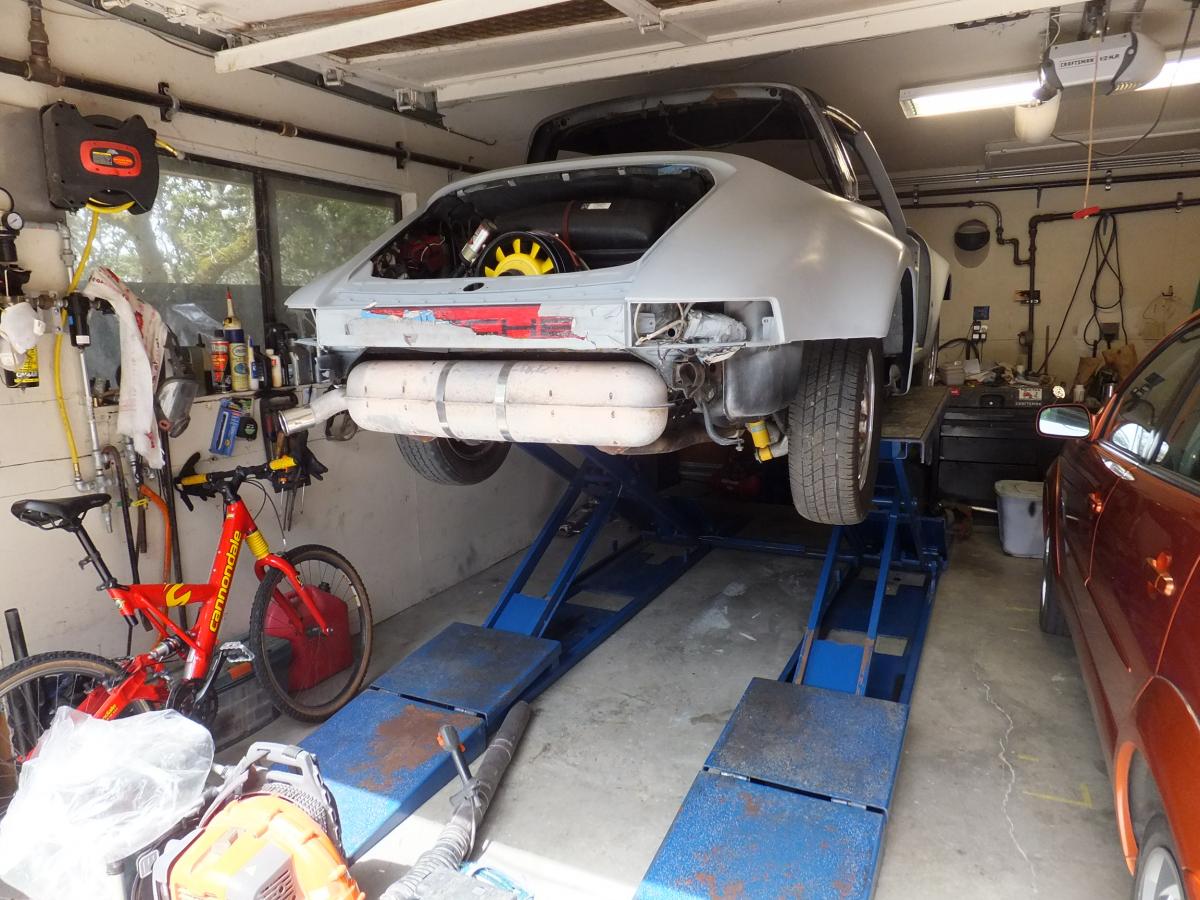
Great questions John …. Yes, safety locks at your desired height ….This BenPak lift uses an auxiliary shop air supply line to actuate a solid chunk of heavy metal tooth that rides over the top of an opposing solid "step piece" that is set into the lift foot base and the solid heavy metal tooth rides over the top of and sets for each 4-inches or so as the lift rises. This sliding lock action secures the lift as it goes up the steps and effectively locks the assembly at each 4-inch stage. To lower, the control tower as can be seen in the photo has a air actuated push button on the console. To lower you first raise the lift slightly enough to disengage the metal locking tooth and then push the air button and hold, then begin to lower. It will automatically lock the tooth at any desired height by releasing the air button allowing the tooth to once again bite into the step locks. Each side of the ramp has this locking/air mechanism so as the lift rises this lock system engages. 7,000 lb capacity to 7-feet high. Yes you can leave it on the floor when not in use and drive over it at anytime and just use it as a parking bump if you will. The lift surprisingly lowers to a height of around 5 1/2 inches. There are heavy removal ramps forward and aft for each ramp. The dead weight of this unit is 2,300 lbs. So once it is set it's not going to slide around on the floor. I bought this one as used and rented a tilting flat bead trailer with ramp to get it home and backed it up to the front of the shop. Then used my winch setup as explained above to pull the entire unit off sliding down the ramp onto my shop floor. Then used the winch to position into place. Some folks, cut out a rectangular section of their garage floor, then form up and place reinforced concrete so the lift itself can be lowered into it so the ramps are slab height. This lowered section is about 6 inches deep once formed and in place, but driving over it with GM steel and the height of our cars is no problem including my 2001 full sized Buick. The Porsche pictured had no clearance problems as well but as shown has not front or rear bumpers attached. The guys with lowered cars like the idea of cutting the slab and placing the lift down so their cars can easily drive over the top of the lift since it is at slab height. Neat trick but I would only do that if I had a duty purpose only shop and not as a garage/shop combo. Oh God maybe someday, please I will have a dedicated shop/studio setup. The BenPak folks want you to bolt the lift to the existing slab but it can be use without the bolts. - dave
-
Here is a photo of my Bendpak lift in my shop. Although the 7,000 lb capacity lift goes to 7-feet, due to my limited 8-foot ceiling height I can get about 40-inches of workable clearance and in only a matter of minutes. I use 4-rubber blocks strategically located so the frame is off the ramp which allows me to work under any portion of frame or sill area :


-
… before getting my expanding BenPak 7,000 lb lift …. I always and still do use a simple setup consisting of the following : 4- metal ramps, one inexpensive high lift rolling 2-ton jack ( One which allows one to take the round single jack point bagel pad that comes on the jack and purchase an replacement attachment which is an adjustable width single arm with bar with dual outrigged bagel pads) . One 25-foot towing cable preferably a fabric one so it does not abrasion your under-carriage components. Also purchase an inexpensive winch. As an anchoring point for the winch use a metal concrete form stake that is slipped into the garage slab. To accomplish that, one simply uses a roto-hammer with a 7/8-inch diameter bit that drills a simple and clean hole in the garage allowing for the inserting of the steel concrete form stake into the slab. This simple setup allows one to slip the neck ring off the winch over the steel stack creating a solid pull anchor for the winch. So when the winch is pulling it is securely set and the pulling force is countered by the steel stake. Use an 18-inch long metal concrete stake, hammer it down into the hole using a small sledge hammer being sure to leave at least 8-inches of stake protruding above the garage slab. A vis-grip will remove it anytime later whenever you need to. If installing into a garage, I place a minimum of 6-8 inches from the edge of slab from the foundation stem wall. This setup is reusable or can be permanent. Works like a charm every time. Set either 2 x 4 blocks or use bolts to keep the front ramp/block assembly from sliding forward on the concrete slab as you winch the car up and forward. Winch pull the front of the car up onto the ramps and then use the rolling jack to lift the rear and set the rear ramps into place making sure to rotate the ramps 180-degrees from the front ramps as an additional safety precaution so the car won't be able to roll backward. Set the emergency brake. Regarding the metal ramps : For additional height other than what the 6-inches height a ramp will give you. I use 4 x 12's & 2 x 12's cut to the appropriate length and cut them to extend at least 8-inches longer then the length of the metal ramps. If the car is not operable the winch and winch strap can be used to pull the car into the garage and up onto the ramp setup. This will give you the 9-11 inch standard curb height as measured from the slab to the bottom of the frame plus the height of the metal ramps and the height of the number of wooden members you wish to place under the ramps. In the first two photos the winch location can be seen in front of the car. It was used to pull the car up onto the front ramps. It will pull the car up with the ramps along with a setup that include 4 x 12's and 1- 2 x 12. I set The rear ramps as stated above were placed by lifting the rear end with the single beam jack and simply placing the metal stands/wood under rear wheels. The height of this setup pictured below allows 18-1/2 inches as can seen of free workable secure space. As stated If additional height is required than add more 4 x 12 or 2 x 12 as desired : .


-
… Oh and if anyone ever wondered what color the factory power brake vacuum reserve tank was factory painted take a look after just washed off with dish soap and water:

-
A closer looksie : … and once removed :


-
Driver's side with shims inserted …

-
Taping up of the fender washers in pairs to achieve the coil gap thickness needed:

-
… Update …. " I removed the springs by hand !! ….Yesterday finally got the springs off and by hand - no tools required ! For the last couple months I have been working out in my house gym and using the hand grip springs and chest pull springs to build up my grip and ability to pull things apart like old phone books and to crush old propane canisters …. Boy has that payed off on this job … The heck with all this wedge shim crap and factory tools this n that malarky … just took a deep breath, grabbed the spring with both hands, took a deep breath, closed my eyes and spread the springs apart … just enough to get them off their perches … the whole thing going down as easy a grandma's best pie …. " … Then I awoke … Apparently I and had fallen asleep on a chair in the afternoon sun while contemplating just how I was gonna do this spring job … the tool bench and car still patiently waiting my approach …. O.K. enough of that … But for real I did get the springs off - Yeah !! … Well the whole plastic and hole saw thing did not work out. First cutting the plastic left melted raised edges along the round cut out using a 2-inch diameter cone bit and required filing … after grooming the first cut out, took it over to the spring and discovered since the spring coils roll over each other a round disk would not feed all the way through the gap and would also require notching on one end to allow the plastic wedge to center in the coil gap. So attempted that and well let's just say that although I was able to create one it took way too long … So had to come up with another plan of attack … I was looking through one of my "this n that" drawers in the shop and came across some large flat 1-1/4 inch fender washers with a 1/4 inch hole and with two stacked together made the same thickness as the plastic ones. Only problem was to do both springs I would need 88 of them, 2 for each spring gap !! Since I was using metal shims needed to protect the paint on the springs, so decided to just use some yellow painters tape. Taped two shims together to accomplish three important issues, namely protect the spring paint, to hold them together and all the while keep them in the spring so they wouldn't drop out. Here is what I discovered ...When you have all the spring gaps chucked with the shims and you begin to raise the hood and compress the spring, it wants to bend and arch inward because the washers cannot go all the way through the coil diameter due to the coiling configuration of a spring so the gap portion not filled which is against the fender line due to inaccessibility will compress more than the engine side of the spring thus creating an acute arch. At first I only lifted the hood a little more than 1/2 way only to discover this and thought the spring may come shooting out off the perches as a projectile … so standing a little to the side and keeping my mug behind the hood front raised the hood all the way up … then carefully and quickly reached in to discover the springs were very loose … so I reached for my pre-cut 2 x 4 and prop'ed into place. Then reached in and removed the springs by hand … so the first part of this dissertation turned out to be true … I did remove the springs by hand !! Well to make this visually attractive, informative and useful because that is what a club is all about I will as everyone knows, have to make a bunch of posts to string this together ( because I invest my money on membership dues not on a personal website ) … So a word to the webmaster who no doubt is marching to the tune dictated by the board of D's …" I suspect the new ordinance the governing of the number of photos posted per post has something to due with bandwidth and cost ? …. If the cost of bandwidth is so cost restrictive when dealing with the posting of photos, then I for one would be more than willing to add to my membership fees/dues while in a community effort and spirit to abolish this mantra of " Photo Austerity " ! Austerity never works because you can simply never save your way out of a hole, yeah you may end up with a less cluttered one … but you will always end up with a less attractive and useful one … But you can invest your way out of one, back fill it and move on - Works like charm every time … " There enough said so on with the show :

-
… Thanks guys I really appreciate the input and all great ideas and thought …. I think the 1/8 inch pilots that Bob suggested above is a great idea and will do that …The shop tool referred to above that I could see was for a 54 Buick and is appears to be positioned on a vertical based spring system …. I too liked the suggestions of Konga Man regarding the inside tube as the springs when they compress after being shimmed will indeed curve out by contractive forces and create a " C - shaped " spring configuration so a solid tube inside would indeed prevent that from happening, unfortunately the forward and rear mounted spring on the perches prevent inserting something large enough in diameter to prevent the spring from arching …. Willy has made another great suggestion and I have a complete blasting setup with various sized crush glass, glass beads etc and will try that when I remove the mechanisms from the car .. I will post photos of the process, what beads I select and we'll see how they turn out … should be interesting. I installed an adjustable air/media control valve at the base of my hopper so I can dial and tweak in the rate of media flow as the size and type of media used demands … a caveat to media blasting the original hinges to that however is there are few minor nicks in the OEM plating and also where hood hinge wear over the years has worn away plating and rust / blush has occurred minor but present just the same ...
-
Great ideas and inspirations .. I have all the manuals and such including the updates but don't recall seeing the J-5537 and if I did most likely forgot about it … (so what's new) . I too like the idea of the round shim approach with a rod in the middle so I hole-sawed my shims and with the center drill bit hole created I will have the ability to insert a plastic rod into the center to maintain integrity of all the poker chips stacked into the spring. I was going to do the extraction today but did not … On a side note since I have newly plated my factory original silver cad fasteners the hood hinge mechanism of which we speak of and even as nice as it is still ( original ) stands out against the newly plated fasteners making it look like I did not finish the process in the engine bay. Damn, thought that since everything was so well preserved minus the rusty fasteners that lined the hood / fender skirt line that I could just get away with plating them and nothing else. Not so much as things just stood out and contrasted too much. Like the old adage once you start painting or improving one aspect of a project it makes the rest suddenly appear to be in need as well where before everything just kinda blended in like the lines in my old face - Ha! … To that thought, last week I did clear coat the lever hinge mechanisms and added some flattening agent to the mix as per my special recipe formulas for doing such tasks in an attempt to see what it would look like and possibly convince myself not to go through all of these calisthenics required to make this happen but even afterwards still the hinges did not look right. Another maddening neurotic alternate reality would be to apply flattened clear to the new fasteners to tone them down to a more pleasing match to the original hinge mechanism …. and move on with the project ! - dave
-
Thanks for that … if things go right I plan on inserting the shims with the hood completely down and the springs at their widest expanse, then raise the hood and hopefully just hand remove the springs from their end perches and all the while hold the hood up with a 2x4 cut to length …. once the springs are removed I will close the lid and remove the 4 bolts holding the hood onto the latch plate assembly and remove the 3 corresponding bolts on the firewall and remove the hinge then repeat the same on the other side … after plating the hinges just perform the process in reverse … i have complete access under hood when it is closed otherwise if the front end was on with radiator and the works this procedure could not be performed unless the fender well skirts were first removed … mine are off my car as well … - dave
-
Hey Al good to hear from …. No my springs are painted and in excellent condition as the factory did not silver cad plate them but enamel painted the springs a kinda dark gray black … So need an approach that will hopefully preserve the integrity of the good paint on the springs … yes your right that it would indeed be a dilemma to have the shims wedged into the springs upon removal and then attempt to have them plated … If one just wants to paint the springs and not remove them from there perches this would best be accomplished with the hood nearly closed if access under the hood can be made or as close to closed while still having access to the springs as they are stretched open at this point and can be painted and have about a 1/4 inch space between the coils then let dry before reopening the hood and collapsing the springs … regarding the hinge mechanism these were however silver cad plated and silver cad plating overtime turns kinda a milky light battleship gray … kinda like gray galvanizing without the chunky or crystal pattern that galvanizing invokes. I send my hardware down to Van Nuys Plating in Southern California one of the few places that still do the true silver cad plating … they do a lot DOD stuff as well to .0005 spec or greater. I initially tried using some wood shims but did not saturate the entire spring so will be attempting this method of using plastic shims made out of TAP Plastic remnants I purchased for a couple bucks in two different thicknesses. When I get the hinge mechanisms out i will wire the hinge in the open position and instruct the plater to plate them as wired. That way when the hood is opened the entire hinge components will be properly plated. I will also instruct the plater to position his anodes so I get at least no anode burn on the surfaces that can be seen from the engine bay …. - dave
-
… thanks Bob for that input … So you say that shimming out the entire spring will allow one to take the spring off the perch easily ? …. I have already tape outlined the hinges where they meet both the heater box and brake booster box on the driver's side and was planning of inserting pegs into the holes just before removal as I take out each of the 3 bolts that hold each side on and replace with a peg … I will photograph the process and see if this will work … But If anyone wants to show up at my place to help out …. all the beer of your choice and smoked BBQ to your liking ….. - dave
-
… small craft airplanes sit on the tarmac for long durations and not are air cooled either. Marine engines sit for long periods of time a well. Go to your local municipal airport and get 4 5-gallon gerry cans full of the 100 or 110 octane leaded or local marina and get pure unleaded non-OH fuel and use that fuel when storing the vehicle … or use it to "cut" into your regular gas mix during the summer R-OH or pure non R-OH gas sold by your local pump jokey. About a 10% mix ratio and your factory compression/spark advance pinking and R-OH percolation problems should cease or be minimal at best. Also keep in mind that one cannot add anything in any ratio to R-OH fuel to keep it from what it does best, namely sucking up the moisture out of the atmosphere or from acting as a corrosive low pH solvent on rubber, plastic, epoxy, urethanes, enamels, tin metals and porous metals.
-
Creating a plan of attack to remove my factory engine hood scissor hinge springs and then the hinges themselves off of the firewall. I will be silver cad plating them so removal is necessary. One caveat I have is my factory springs have excellent paint still remaining on them and do not want to beat, pry or pound to get them off of their perches to free them from the hinge. So with that said, would like to hear of any workable tried and true solutions you have actually applied to your spring removals. One method I have thought of is to protect the integrity of the spring and make it theoretically easy to remove the spring is to insert 1/8 to 3/16 thick pieces of cut plastic tabs into each ring of each spring so when the hood is closed this should take around 10 inserted pieces per spring. The springs are stretched out when hood is closed so when the hood is then raised the springs will not be able to compress and the springs should theoretically be able to be removed with minimal prying required. I have access to the under side since my front end components have been removed and I have access to this area when the hood is closed. When I get the plating done I will mount the hinges back onto the firewall with the hood closed then with the hood open remount the springs. That way I believe can make this a 1-man job. - dave
-
I would Post on the AACA Oldsmobile " Post War " section of their site …. http://forums.aaca.org/forum/32-oldsmobile-buysell/