Gary_Ash
-
Posts
2,295 -
Joined
-
Last visited
Content Type
Forums
Gallery
Events
Everything posted by Gary_Ash
-
I took one more look, found another related patent by Edward Fonseca and assigned to Wilcolator Co. See http://www.google.com/patents/US1772279 I don't think Wilcolator is still around, trademark expired in 1986 . Google indicates they made a lot of thermostats and controllers for domestic ovens over the years. Fonseca has a number of patents from back in the 1920s-30s, all assigned to Wilcolator, so I assume that he was an employee. I'm not sure how Flash Semaphore Co. fits into the picture, was unable to find anything about them, maybe they were a licensee. Do a Google Image search on Wilcolator and you'll be entertained for hours. Here's their mascot, Reddie Wilcolator:

-
I usually have better luck using the Google patent search. Google has scanned many, if not all, patents back to the first ones and performed optical character recognition so that the text is now searchable. However, you still can't search them by inventor name or assignee, like Flash Semaphore Co. I did come up with patent 1699104 issued in 1929 for a color-changing temperature gauge. The working principle is not one I would have guessed. This could be it, but maybe not. You can download the PDF file to see the drawings and text in full detail. www.google.com/patents/US1699104
-

Wanted to Buy 1928 or 1929 Model A Ford Tudor
Gary_Ash replied to a topic in Automobiles and Parts - Buy/Sell
Here's a picture of a 1929 car that recently came on the market in the Boston area. It's an older owner-restored car, very nice as a driver. Send me a PM if you are interested and I'll put you in touch with the owner. It's not mine. Be prepared to make an offer.
-
Based on the cylinder head number, it appears to be a 1931 Model 54 Studebaker Six or a model 41 Rockne.
-
Yes, John, I've done it before on my 1948 Studebaker M5 pickup truck, including the odometer wheels. I made water-slide decals on a color laser printer, coated them with water-base acrylic varnish for protection. For ink-jet decals, I use Krylon clear, but the Krylon will destroy laser-printed stuff. White numbers on a black background (or on glass) are a little tricky. Here's a page on my web site that describes it: http://www.studegarage.com/instruments.htm I made the CAD drawing of the instruments in preparation for restoring the ones I have. I was just hoping I didn't also have to re-do a brand new gauge, especially since the modern bezels are crimped on tight all the way around. Sigh!


-
After a lot of traveling, I finally got back to finishing the frame modifications. My first attempt at fishplating the cut-and-welded frame rails didn't pass review, so I ground off the small plates and had some bigger plates laser-cut from 3/16 steel plate. There are ten 3/8" diameter holes in each plate where I welded the 1/8" thick frame rails to the fishplate. I added some lengths of stitch welds around the outside edge of the fishplate. A 4"x1.5"x1/8" plate was formed to fit inside the top flange where it had been cut and re-welded, and this got stitch welds around the outside. Each weld was hammer-peened while hot to relieve stress. A little grinding was needed to clean things up. The rails came out straight and, for sure, they'll have enough reinforcement now! I also added a CAD image of my planned instrument panel. I have most of the Stewart Warner instruments from a 1931 or '32 sedan, just need a tach and oil temperature gauge. The current Stewart Warner "Wings" series has the right while-on-black markings and arrow/crescent needles. Too bad they used the wrong typeface!


-
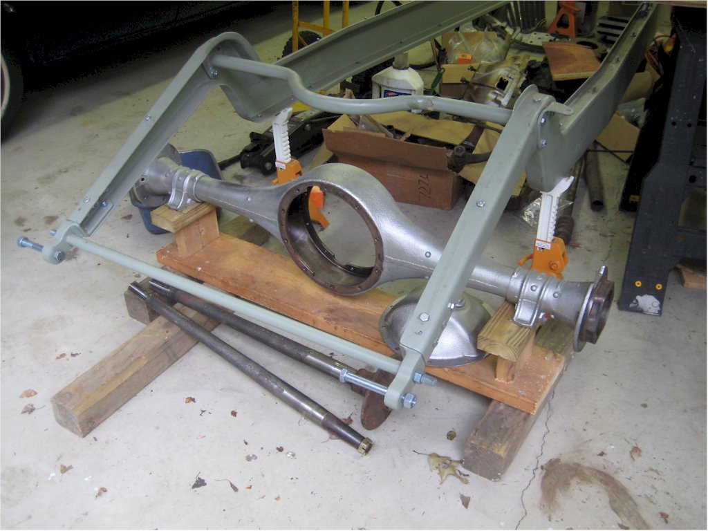
Ed: The original 1931-33 Studebaker Indy cars used the 337 cu in President straight 8. In the 1933 race, the five factory cars were beaten by an independent entry running the smaller 250 cu in straight 8. Due to the depression, production of the 337 cu in engine was cancelled for 1934 and the factory was developing a racing version of the 250 engine when bankruptcy ended Studebaker's Indy program. At least one of the engines was installed in a factory car for tests. A few completed race engines were sold off, current locations unknown. My engine will be one of the Studebaker 250 cu in straight 8's, as used from 1929-42 in Studebaker sedans. I found a couple of 1937 blocks to use - they look the same externally as the early engines, with the water pump on the left side. These used insert bearings in the 9-bearing crankshaft mains and also in the rods, unlike babbited mains of the earlier blocks. I've got one 7:1 compression aluminum head. Using old photos and some measurements from the existing Indy cars, I designed and made cast aluminum intakes for four Stromberg EX-23 carbs, as well as the linkages. The cam will be a hotter version of the stock cam with longer duration. While the original engines used a magneto because they didn't carry batteries in the cars, I'll stick with the stock dual-point distributor. My engine will look pretty close to the one shown below in the 1934 photo. Expected output will be 190-200 hp at 4000-4400 rpm, 250-260 lb-ft of torque over a broad range of rpms. I've got a 1938 President 3-speed transmission, one of the "sideways" boxes with synchromesh. Gerry Kurtz can add an overdrive to it for me, if I decide I need one. Rear axle is from a 1928 Studebaker GB commander coupe with stock 3.31 ratio. With 7.00-18 tires on the rear, that should be good for more than 115 mph, without overdrive. I picked up five NOS axle shafts from Nelson Pease in Palmer, MA, passed along two of them to Bob Valpey for his #37 car. The original factory cars used the same axle with 3.09 ratio. Front axle is from a 1929 President FH sedan, about the same as the originals. My steering box came from the same 1929 President donor car. Ed, I was in your shop in September with the other Studebaker guys on tour, if you remember.


-
Call Bob Munter in Northborough, MA at WCD Garage, where they repair and restore Studebakers and other cars. He also runs a parts business known as Northeast Studebaker. He has many, many NOS parts, including sheet metal. Bob restored his '51 Commander to a 400-point car. He'll be at York, so could bring the right stuff for you. Call him Mon-Fri 8am-5pm at WCD Garage, fyve oh ate-393-2493.
-
How about a longer blade and a fine-tooth hacksaw? Also, try John Boschetti, who specializes in pre-1966 wipers. He's in Mass., phone is sebn ate won - niner won tree - tree for niner niner (mobile).
-
1914 Studebaker body parts wanted
Gary_Ash replied to crazycars's topic in Studebaker, Erskine & Rockne
Have you talked to Ray Helger on Willow Ave? I was at his shop recently, he had some 1917 Studebaker pieces. But, wait till the weather warms up a bit because Ray didn't want to go roam through the barns looking for parts in the cold. -
You need to call "The Temperature Gauge Guy", Roy Martin in Burlington, VT. His number is ate oh too 862-six tree sebn for.
-
You may not need a 2-part die. You can make the female side and hydroform the part. A thin metal sheet, e.g. brass, is placed over the die and 60-90 durometer urethane pad is placed on the back side. The die, sheet, and pad are placed in a heavy-wall pipe and big steel pusher plug is loaded on the back side. A hydraulic press pushes down on the plug and forces the brass sheet into the die. I made a 4" diameter rosette for my Indy car project using a 6061-T6 aluminum die. My little 12 ton press isn't quite enough to get all the details sharply pressed, so I gave it another shot with a 30-ton press. You might get away with a 50-ton press on 6" diameter. Anything larger will take a big press. There are many commercial companies who can do this. A commercial 3D scanning service can scan your existing hub cap and give you a 3D CAD file. Then you just need a good tool and die shop to translate that into the die. The hydroform companies can probably do this for you. Be sure to bring a bag of cash.


-
Gee, you guys are TOUGH! But, I know that you're just concerned for my welfare and worry about weld cracks, thank you. So, I laid out a bigger, longer plate for fishplating both sides. They will be made from 3/16" thick A36 steel plate with a bunch of 3/8" holes to plug weld the plate to the 1/8" thick web of the rail, as well as welding on the edges. I took the DXF file of the fishplates down the street a mile to the metal cutting and fabricating place. They'll laser cut them early next week. Each will weigh 1.6 lbs. I'll go grind out the little fishplate... I had been getting a bunch of other parts ready for them to cut and bend, so I took a bunch of DXF files. The laser cutting is excellent, narrow kerfs, dimensions on 3/16" and 1/4" thick plate to within about 0.005". I don't bother to drill holes, I just have them cut them in. That way, they are exactly in the right place. I don't even have to ream for bolt holes. They'll be cutting spring shackles, steering box mount, formed plates to go under the rear springs and mate to the shocks, brake backing plate adapters, etc. I'm using TurboCAD for all the design work, by the way. As I need good CAD for business use, I got the top-end Pro Platinum version and run it on a fast PC. However, even the TurboCAD Deluxe basic version at $129.99 will do 2D and 3D. They offer pretty good deals from time to time that are well below the "list" prices. I'm drawing all the parts and pieces as I go, so I'll have a complete car as a 3D CAD model when I'm done, as well as the real thing. Assembling the parts in CAD has helped me find some errors before I started cutting steel.

-
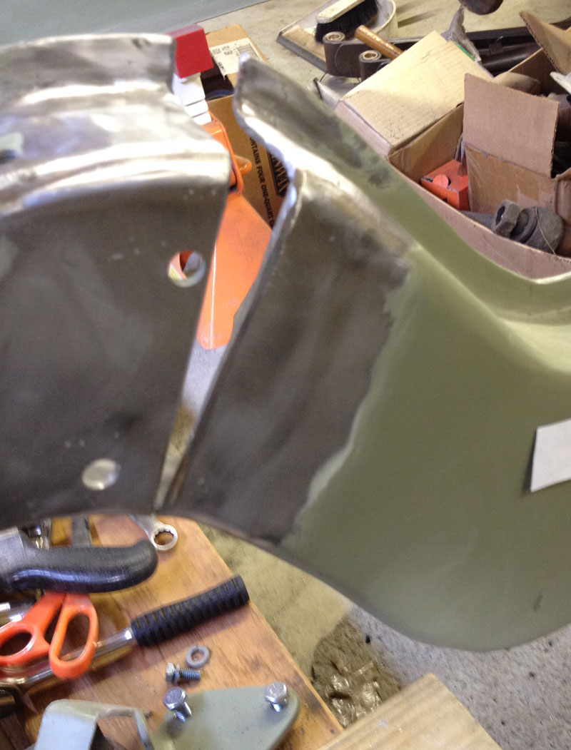
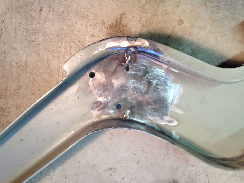
I'm glad I put a 60,000 BTU/hr Hot Dawg propane heater in the garage last year! It was 6°F here this morning, warmed up a little by mid-day, but I needed the heat to work. The cuts I made were about 1.33" wide at the top flange, enough to rotate the frame a full 16.5 degrees and get the shackle eye where it really is supposed to be. I made the second side cut, dressed up the cut edges, and put my jack under the tail section. Of course, the whole chassis lifted off the jack stands, so I placed a pair of the new rear springs across the frame rails just in front of the cut. I was pleasantly surprised to see that I could jack the rear up and have it pivot on the lower flanges, which I had not cut, no heat required. It took a few up-and-downs while I trimmed to get a uniform gap of about .040". I lined things up, clamped it tight with some ViseGrips with a 1/4" thick copper plate behind the web, and started tacking. As I expected, laying down some beads about 1" long, alternating sides, pulled the gap closed even more. I hammer-peened each short weld bead as I went, to stress relieve. Once the welding was mostly done, I took the chassis apart - a bolted assembly has some advantages. This allowed positioning the inside joints for the best weld penetration. I ground down the outside and inside (web only) to get things flat and smooth. I left the inside weld bead untouched at the top flange for extra strength. I was too lazy to follow DavidAU's advice to cut out a longer pieces of the top flange to avoid a straight weld, but it's very good advice if you have to do this some time. I welded in a 4"x2"x1/8" fish plate across the weld zone on the back side. It's kind of a Band-Aid, but at least it's something. So, I am happy to report that the shackle eye came up exactly where I wanted it, the rails didn't twist, and the welding went well. Here are photos. And just for frosting on the cake, UPS delivered the splined wheel center I ordered from England on Monday. It's 8.25" diameter, 5.5" high, has 0.2" wall thickness, and weighs 5.5 lbs. It's a nicely-made steel part, looks like it was machined from a solid bar of steel - which would have started at more than 90 lbs. We'll use it as a gauge to check the fit on the splined hubs.


-
Wow, Commodore, that was some good searching! Now I just have to find a copy. However, based on the one page I do have that has the chart of some dimensions, they don't agree with what some vendors are offering. I am anxious to get a copy of the article because it will help to provide some more background. I sent off an email to the editors of the "Bulb Horn" requesting a copy. The wheel center I ordered arrived today, made it from England to here in about 36 hours. It will be perfect as a gauge to check the machined splines. It looks like it was machined from bar stock and the splines broached on the inside. It's 8.25" o.d., 5.5" tall, 0.2" wall thickness, weights about 5.5 lbs. The photo of the grooves is a little deceptive because it exaggerates the groove depth since it shows where the grooves intersect a tapered surface. It's quite a piece of machining. I believe that it was made in India.


-
Plan A: I'd place the flat sheet on a scanner to get a high-quality JPG image. This might have to be done in two shots, or go to an Office Depot where they have a big scanner. Use a known resolution, something like 300 dpi. Then, bring the JPG file(s) into a CAD program or Adobe Illustrator/CorelDraw, set the image size to equal the actual part, and trace over it. Take the artwork file (.AI or .DXF) to a good sign shop with a vinyl cutter and have them cut a thin, peelable mask. Assuming you have the part already re-plated over its full surface, very carefully strip the mask areas that will be painted and apply the masking over the lines. Alignment will be a challenge. Use lots of little rosewood manicure sticks and plastic tweezers, etc. to be able to massage the mask into place and rub it down gently all over. Spray the paint and let dry a few hours. Strip the masking before the paint gets really hard. I think I'd get a couple of masks cut and practice this on a dummy metal sheet first. If you do screw up the painting, you'll know when the strip the mask and there will be a little time left to remove all of the paint with solvent and start over. Plan B: Make a new plate. Once you create the lines in the CAD or Illustrator file, invert the lines to make them transparent, fill the open areas with a brownish color (if that's what the original is/was). Save a JPG image at high resolution, say 300 dpi. Send the file to a company that prints durable photos on anodized aluminum. You might find someone to print on a plate where you have already machined the holes for the gauges, otherwise you'll have to get it machined afterwards. Walgreen's will print a 16"x20" panel for $49.99 Plan C: There are some materials that are directly laser engravable. It's shiny metal, aluminum or stainless, with a layer of paint on top. I'm not sure if the brownish color is available. The laser burns the paint off, exposing the shiny metal. Chuck Collins at www.studebakerparts.com has a laser engraver and could do this for you once you have the computer file. Here's a photo of two versions of a Nagel gas gauge face that Chuck engraved for me. One has a black background with metal lines, the other is metal background with black lines. I had re-created the artwork from the old, faded gauge face.

-
Bill: As a matter of fact, I just sent the library an email with a research request. I wonder if that article appeared in the AACA magazine. I did ask that they check the 1974 volume of Antique Automobile. If it wasn't in the AACA magazine, they may still be able to find some info for me. Good suggestion!
-
David: Thanks for the photos and sketch. I am a bit confused because the splines on your cars look square and I thought the splines were V-shaped based on an article by Alec Ulmann back in 1974. Here is the only page that I have from the article, maybe someone will recognize it and have saved a copy for 40 years. Your dimensions, and the ones listed on the web sites of various wheel vendors, are different than the ones in the Ulmann article, but there do seem to be many variations on the theme. The 20 mm dimension for the length of the conical seat is very helpful as a guide. I have ordered an extra wheel center so that I can examine it in detail before sending in the machining drawings for the hubs; it should be here in a few days. I have been told that hubs made in Europe use EN8/080M40 (= USA type 1040) or EN24 (=USA type 4340) steel. I'm planning on using 4140, normalized before machining, heated, quenched, and tempered after machining. The 4140 is a standard chrome-moly alloy with high strength and good machinability in the normalized state.

-
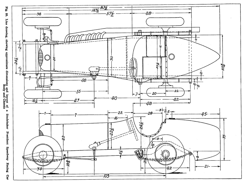
Here is the drawing that appeared in an article by Ray Kuns in 1935. The 15-page article gives many specific details of the Studebaker Indy cars. Of course, in 1935, you could just go down to the junkyard and pick up the parts you needed - no more! His various books have a lot of useful information about building speedsters and race cars in the 1930s and later. The actual wheelbase will be about 103". I was aware that there were a number of discrepancies in what he drew vs. what the actual dimensions were, but the drawing is generally pretty good. Errors that I now know about include his depiction of the cockpit width extending to the outside of the frame rails when it actually goes to the inside of the frame rails, a difference of about 4 inches. He may actually show the body width dimensions correct while drawing it wrong. The other error, which seems to have led to my problem with the rear section of the chassis, is that he shows the eye of the rear spring hanger (where the shackle goes) to be below a line extended from the lower edge of the frame rail. I think my chassis builder relied too much on the Ray Kuns drawing and not enough on actually measuring the Studebaker car at the Indy Speedway Museum. Note that the Kuns drawing shows the rear shackle in an inverted position. I think a spring can be made to work that way, but I haven't found any photos of the cars that show a spring and shackle mounted like that. I suspect that Kuns got a day with the car, made a bunch of sketches and notes, then found that it didn't go together right when he made the publication drawings, so he faked it with the shackle. So, now I have to use the hacksaw and welder to make up for the mistake. I've got one side cut and weld-prepped, will get the other done this week and try bending it to where it needs to be.

-
The splined hubs to hold the front wheel bearings and the 1963 Buick Riviera brake drums have been a real pain to design. Originally, I planned to make an inside hub to hold the bearings and the drum, then use the 5 bolts on the drum to hold an external splined hub for the wheels. The problem was that I couldn't design the external hub to go over the inner hub near the drum surface and still have enough metal thickness to feel comfortable. I finally gave up and made one splined hub adapter that takes the two bearings on the inside, has splines on the outside, and holds the drum and wheels. These will be machined from 4140 steel, normalized before machining, then hardened and tempered to be really strong, tough, and pretty hard, but not brittle. Amazing how problems can be solved by the simple application of many design hours and cubic dollars! The front hubs have the pockets for the bearings, the rear ones just have a tapered hole and keyway for the axle shafts. Of course, the rights are threaded different from the lefts, so that makes 4 individual - and different - hubs to be machined. This is an exercise in reducing a 40 lb hunk of 6.5" diameter steel bar to about 7 lbs of useful material. Most of it can be done in a decent lathe. The hard part is cutting 112 little splines around the o.d. of the 3.6" diameter tube. They have be exactly the right profile - not exactly a gear, but close. A few small companies around the world make splined hubs for cars like old Jaguars and Bentleys, but no one will tell you what the dimensions ought to be, especially for the nominal 72 mm size. Rudge-Whitworth invented and patented the splined hubs about 1912, so it's not like it ought to be a big secret, but it is. Anyway, I think I have a set of good-enough dimensions and I ordered a spare wheel center to be used as a gauge for machining the hub splines. The wheels and hubs WILL fit together!


-
I bought a set of those gauges for my Indy car project, haven't restored them yet, think they are 1932 but I'm not sure. The thin, flat, oval sheet may be embossed, nickel-plated brass. I say that because the lines are shiny metallic and seem to be raised from the painted/lacquered areas. I can just feel the lines with the edge of my fingernail. Maybe they stamped the sheet and nickel plated it. I suspect they may have used photosensitive material to make a pattern over the lines, spray painted, and removed the masking. Restoring it like that will be tricky because it can't be sanded without destroying the lines. If it was embossed, the back side should show indentations where the lines are. If there are no indentations, then they etched the metal with the photoresist protecting the lines, then painted. The paint or lacquer was a very thin layer, looks "greige". Sorry, I haven't disassembled mine yet. The hood over the gauges appears to be thin, nickel-plated steel, crimped on to the plain steel back housing. It seems to be plated all over, though mine has that "patina" of age that makes it hard to distinguish rust from something else brown.


-
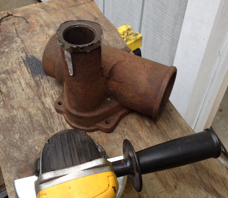
As a matter of fact, I was just taking a well-earned break from hacksawing the frame. I finally decided to bite the big bullet and move the frame ends up the full 7 inches. This places the rear spring eye a few inches above the front eye, which is supposed to give better handling. One day, after I lap Indy at 140 mph, I'll let you know if I did the right thing, LOL. I'm almost done cutting the first side, will soon move on to the second. I'm leaving the bottom flange intact, don't know if I can bend the frame ends up without heat or not. Should I ask my wife to lift up the back of the chassis while I use the torch or should I ask her to heat the frame rails? Maybe I'll just get the come-along and leave her to the gardening... The set of 4 new springs arrived from Eaton Detroit Spring. Mike Eaton was easy to work with, did good work, shipped the springs in about 2-3 weeks. I'm working on the design of the various hangers and shackles. It was easy when they were abstract parts, but now that they have to fit EXACTLY, a lot of attention to detail is needed. The springs came with bronze bushing, including grease grooves. I'll get drilled, greaseable bolts to keep things lubricated. Fortunately, the off-road Jeep guys use them in their urethane bushings, so they are pretty cheap to buy. I wouldn't want to drill a Grade 5 bolt down the middle, cross drill it, and tap for a grease fitting, especially not 12 times (4 springs x 2 eyes plus shackle hanger points). I started on the steering box. The original Ross unit from a 1929 President had a big rectangular flange. The Indy cars cut the flange off, turned the end of the part that holds the shaft for the Pitman arm, and put it in a big clamp. I think that was so the height of the wheel could be adjusted to suit the driver. I cut the flange off with an angle grinder, took away most of the excess meat, and my buddy turned the o.d. to 1.875". I'll make the clamp out of a weldment of 1/4" plate and some bars. Another big moment was when I gritted my teeth very, very hard and ordered the 4 wire wheels for the car. These will be real wires with splined hubs and knock-off spinners, just like the old days. It took a lot of research to find out what size wheel to specify and the dimensions for a good splined hub, especially one to hold the inner and outer bearings on the front spindle. Here's a CAD image I made of how the wheels will look. Now, I'll have to do a lot of extra consulting work to pay for the wheels! Ouch. I've been busy!


-
Yes, Gary Morton at Vintage Rims in New Zealand is very helpful and knowledgeable , but he didn't have the spline dimensions for the 72 mm hubs. I suspect he makes the rims for many of the other wheel suppliers.
-
I want to use Rudge-style wire wheels with knock-off spinners on my project to build a replica of a 1932 Studebaker Indy car. Because the front spindles are large in diameter, they take large bearings and cups, which has driven me to the 72 mm size of hubs and wheel centers. I can find people to build the wheels [for a price], but no one seems to have a drawing for the proper dimensions of the splined hub that the wheel goes on. I'm looking for dimensions taken from drawings or real parts. The 72 mm size seems to be rare. The people who actually sell some hubs of various sizes seem reluctant to share even basic dimensions. Because of variations in bearing sizes, brake drums, and wheel offset, splined hubs are made to designs unique for each car, and the front ones are different from the rear ones. And, the right and left sides get right and left threads for the spinners. Bolt-on hubs, particularly the current Dayton style, are a little more generic, but I didn't find any that would fit, and I still have to make hubs anyway. Wheels will be 18" x 4" wide with 70 spokes. Tires are 6.00-6.50/18 front and 7.00/18 rear, probably the new-style Excelsior radials. While currently most of the hub and wheel parts are made in Europe or Asia using metric dimensions, you can bet that the Rudge people used inch sizes for everything when these were developed about 1908-1912. In particular, the spline circular pitch is 0.1 inch. Thus, the 72 mm hubs with 112 splines have a base circle of circumference 112 x 0.1 = 11.2 inches or a base circle diameter of 3.565". The individual splines are about the shape of a 60-degree thread with the tips and roots filleted to .016" radius, rather than sharp edges. The splines undulate up and down from the base circle. The resulting outside diameter is 3.62" or 91.9 mm and the root diameter is3.51" or 89.2 mm. The splines are something like 43-55 mm long, depending on who you ask. The wheel center has a mating spline, and it slides on until it seats on a 60-degree cone at the inside end. The outside of the hub has 3.5"-8 tpi thread for the spinner, and I think it is supposed to extend about 1/2" beyond the hub. I think there is supposed to be a ~10 mm gap between the threaded section and the splines and also between the splines and the start of the cone seat, but this isn't certain. Most of the dimensions I have came on a tattered copy of a page from a July, 1974 car magazine of unknown name in an article by Alec Ulmann - I wish I had the rest of the article. I'm trying to be sure that I have hubs machined so that the wheels seat on the cone and spinner tightens it down correctly while centering the outer end. I think the big Bentleys from the 1920's and 1930's used the 72 mm size, maybe some U.S. cars. Does anyone have these dimensions for a 72 mm hub?


-
Looking at the photo of the maroon #22 car, the rear spring eye is much higher than the front eye. This would be the result if I bring the rear up a full 7 inches. I thought that best performance occurs when the spring eyes are at the same height, but I am very open to opinions on this. Bringing my current rear spring eye up about 3.8 inches would level the spring eyes and bring the chassis rails level when the car is loaded with 2 passengers and gas. The front springs will be very stiff and the rear ones much softer. This should produce good roll resistance and good steering, though a very stiff ride, especially with bronze spring bushings and greasable bolts. The springs and bushings have been ordered, should arrive next week.