


John Jacques
-
Posts
83 -
Joined
-
Last visited
Content Type
Forums
Gallery
Events
Everything posted by John Jacques
-
I am having a difficult time trying to find the correct way to install the food hinges/springs on my 46 Ford [pick up. Is there anyone that could provide a photo of the hinge assembly installed, It would be greatly appreciated. Thanks, Jakes
-
1937 Buick 46S Coupe for sale and I am asking $29,500. Complete off frame restoration completed this year. Below are a few photos:


-
Well, here it is nearly 6 months since my last entry. On and off during this period I attempted to resolve my light flickering problem. After taking everything apart and checking all connections I located the problem. It turned out to be the wiring within the right head lamp socket. The springs and wiring in that socket corroded. I replaced the wiring and cleaned the springs. Viola, everything is back working as it should. I apologize for taking so long, and hope I never have to go though this again. Thanks for everyone's help.
-
Just ordered the 201. I'll update progress after installation. Thanks to all !!!!!!!
-
The 1118213 that is on ebay is for the original 37 generator and that regulator only has two cores (or units). If I'm correct after reading all the information from this and other forums, I'll need a 3 unit regulator, seeing that I have a 2 brush generator. Perhaps Bloo's possibility of using a 201 or 301 regulator maybe the way to go. If they are a three wire regulator I guess the thing to do is ground the ground wire from my 4 wire to a separate ground, as they probably is no ground wire terminal on those regulators. Replies......
-
This is why I like using this forum, I alway learn something that I did not know, and in PLAIN English. As far as the lights blinking go, I'll remove one wire at a time from the headlight switch to locate the problem. Back to the generator/regulator problem. I will keep the 2 brush generator that I currently have and purchase a 3 core regulator. ANY suggestions regarding which 3 core regulator to purchase???? If the 3 core regulator happens to be a three wire regulator, how should it be hooked up? I'm asking this because I went from the original 5 wire regulator to a 4 wire regulator having one extra wire. Now using a three wire regulator, I'll have two extra wires.
-
Interesting! If the 2 brush generator that I have is above 30 amps, won't that amperage effective the thermo breaker on the headlight switch causing them (and other lights) to blink? That is also a problem that I have been working on. If that is the case, maybe I should go back to a three brush generator. Earlier, I had mentioned that I originally had a 315 regulator (2 core) and purchased a rebuilt 213 (2core) regulator that was found to be defective, and I am returning. While searching for a 3 core regulator, I came across an article that the 213 regulator is obsolete and replaced by the 315 regulator, and that one is also obsolete. Luckily I do have the 315 regulator (4 wire) if I would go back to the original 3 brush generator. The repair shop that I took this generator too informed me that it was putting out 28 - 30 amps. I guess I really have to determine exactly what amp generator I do have and if it affects the light issue that I am experiencing.
-
So, now I know that the tag numbers for the generator I provided were actually for a starter not a generator. It was mentioned that the 2 brush generator is an upgrade generator from a 3 brush generator. That said, I guess that I should stay with that, and I should be looking for a 3 core regulator vs. 2 core to be compatible with the two brush generator that I have. I will search through the leftover parts that came with the car in attempts to locate the generator's original ID tag. Keeping this upgraded generator - Good or Bad idea?????
-
This vehicle was purchased from the previous owner while it was under restoration. The chassis was completely restored including a rebuilt engine, transmission and possibly the rear end. The generator was already installed and it did not have an ID tag on it. However, the tag was saved and in with other parts. The (black)tag reads; Anderson, Ind. Delco Remy, Model; 734Z, and serial # 233918. It is a two brush generator with two wires. One to the field (F) post and one to the armature (A) post. The only voltage regulator that was provided was a Delco Remy 4 terminal regulator bearing the number 315, and has two cores. I am aware that the vehicle originally came with a 5 terminal regulator, which Buick only used for a brief time, replacing it with a 4 terminal voltage regulator. I am also aware that the ignition wire would not be used when replacing the system from a 5 wire regulator to a 4 wire regulator. That extra wire has been taped off, as I did not want to cut it off from the new wire harness. Hope this added information is helpful.
-
As I am wrapping up the restoration to my 1937 Buick Coupe 46S, I discovered that the battery was not being recharged. I took the generator to a local repair facility and it was tested good. My thoughts were that it must be the voltage regulator. After searching the shop manual for the correct voltage regulator (Delco Remy 1118213), I realized that the voltage regulator that came with the car only had the number 315 stamped on the case. My next thoughts were to find a 1118213 regulator. After an extensive search I did locate a rebuilt one on ebay for $75.00. I thought that price was a little steep for a rebuilt, but with no other choice I purchased it. After installing it, it was noted that it also was not charging. I then took it, along with the generator to a local repair facility (been in business for 30+ years) to have them tested. I was informed that the generator was fine but the regulator wasn't. I am in the process of obtaining a refund from the seller. My question is that seeing that it is difficult locating a 1118213 regulator, would anyone know if an interchangeable part number is available? Thanks for any help that you may give, Jakes
-
Sorry that I have not gotten back to this topic as I had to take a break, due to other issues going on. There is sooooo much information that was provided from all of you that it will take me some time to perform these tasks. Please be patient and I'll reply with my findings as soon as I can. I really do appreciate all of the responses. Jakes
-
I opened up the floor dimmer switch to see what it looked like. It was pretty clean inside with no evidence of rust or corrosion. I did check it with a Ohm meter and it operated as it should. Therefore, I did not order a replacement floor switch and I am back to scratching my head. I'll probably open the headlamp switch (again) and check out those three triangle once more. Originally, I did not see any difference between the three triangle, but did notice that they all had different numbers on the bottoms. Does anyone know the correct location of this triangle, or does it make a difference? I also saw that there were three springs. One of the springs was a little shorter than the other two. I installed that shorter spring in the center position, as that position had a brass insert with a ball bearing. I have to admit in attempt to correct this headlight problem and prior to disassembling the headlamp switch the first time, I ran 600 grit wet/dry sand paper through the points on the thermo circuit breaker, thinking that would clean them up.
-
Well, I checked out all the wiring for shorts and found all was OK. It seems that the floor switch maybe the culprit here. I am going to order that switch and go from there. Thanks, again for your inputs.
-
Hello sloperlad, yes, I recently had my first experience applying woodgrain to the dash and garnish moulding by using the Hydrographic process. If you're not familiar with hydrographic's, it's a process that you submerge the item in water that has a special design film (woodgrain/patterns/etc.) laying on top of the water. Then an activator is sprayed onto that film just prior to dipping your item into the water. After the item was rinsed with water, then dried, it was clear coated. There are many videos on this subject and it's a project that can be preformed fairly easily. I have attached a photo of the finished dash in my 37 Buick 46s. Good Luck, Jakes

-
Well I checked the socket springs in the headlight and those were fine. Here's whats happening: the first position of the headlight switch (pushed in all the way) nothing lights up or blinks (as it should), the second position (pulled out one notch) the fender lights and the tail light/license plate light comes as it should. In the third position all the lights blink, this is with the high beams off. With the high beams on only the tail lights come on, no headlights, fender lights or license plate lights. In the 4th position with the high beams off, all the lights work fine, but with the high beams on, the left headlight and tail lights blink, no right headlight or fender lights. What do thing the problems is ?????
-
Thanks to all for your suggestions. Later this morning I'll start checking it out and let you know the status. It's guys like you that make repairing/restoring these old gems rewarding and fun. Keep up your good work!!!!
-
Rock10 no, I do not have turn signals installed. Ben, I will do as you suggested. Is it better that I try taking out each bulb separately or disconnect each wire separately from the headlight switch? I don't understand "until breaker stays on".
-
Hello again, this weeks problem: as I'm in the final stages of restoration, when the headlamps are on for about 15 seconds they start flashing, as if I had 4 way flashers turned on. Not only do the headlamps flash, the fender lamps and tail lamps also flash. I double checked if all the lamps were correctly wired and that they had all good grounds. Don't know what else to check. Any suggestions????? Thanks for any help that you can provide. Jakes
-
Thanks Gary, this was very, very helpful!!!
-
Thanks McHinson for your reply ! Prior to my listing this question I went to Bob's website. I did see the clips that you mentioned. What Bob's listings did not provide was what size holes does the clips accept. I didn't want the clips too large that they would chip the paint around the holes or that they would be too small and not tightly secure the moulding to the panel. I will give Bob's a call to find out what clips they recommend. Thanks again. Jakes
-
Hello again, as I am wrapping up the restoration on my 37 Buick 46S Coupe I'm at the point now of choosing the correct body side moulding clips. I have installed the 1/4 moulding, as they were the easiest since I could secure them with a screw type clip from the inside. The door moulding are a different story. I believe they are secured with a push on type of clips, or maybe with barrel nuts (just my guess). The hood side moulding, I have no idea how to secure them. I am hoping that someone could steer me in the right direction on which clips to purchase. Any photos would be appreciated. Thanks again, Jakes
-
Jeff, attached is another photo of the stop, which is a 90 degree bracket. I drilled an oblong center hole in that bracket so that I could adjust it to prevent the hood from sliding onto the grill surround. I did not have any problem with the hood closing onto the cowl. If I had that problem I would have installed a similar bracket as pictured in Gary's photo above. Hope you find this helpful. Jakes
-
Rob, I also experienced the same problem you're having. In reviewing the photo that Gary provided regarding the 38 rear hood stop, I basically did the same but to the front at the grille surround. I fabricated a stop and placed it under the front upper hood moulding hold down. I was able to do this fairly easy without any assistance, and without the need to remove the hood. Now, the hood opens and closes like it should. Hope this helps, and good luck. Jakes PS; the more hands to remove and install the hood, the better.

-
1937 Buick 46S brake/ clutch pedal ?
John Jacques replied to John Jacques's topic in Buick - Pre War
Thanks for that info Rock10. I be sure to install a bolt. -
1937 Buick 46S brake/ clutch pedal ?
John Jacques replied to John Jacques's topic in Buick - Pre War
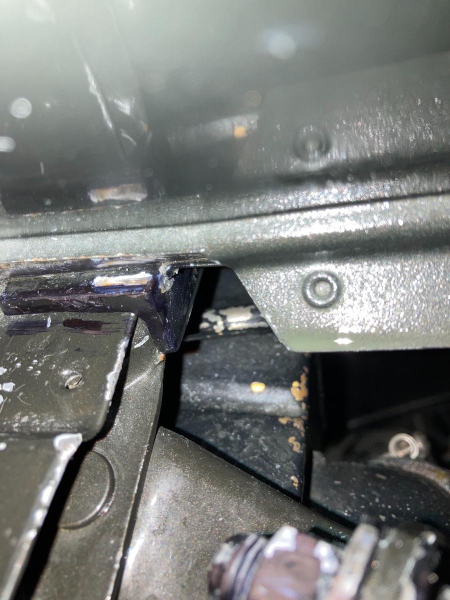
Thanks to all of you who responded. I too thought that the shaft should not stick out passed the brake pedal, and that it was way too long. After a closer look at the shaft, I noticed a corresponding hole in the frame rail that was almost in line with the opposite end of the shaft, short of going into the hole by a distance that equalled the other end that was sticking out past the brake pedal. As to the possibility of using a different floor plate, I contacted Dave Tacheny a few months back and was informed that he thought that all floor plates were the same. It appeared that the master cylinder, pedals, and linkage did line up as it should. Heres the good news!!! I tapped the shaft back into the pedals and positioned the shaft so that it rested inside the hole in the frame, and VIOLA, everything lined up, the pedals were centered between the steering column. ALL IS GOOD!!!! Thanks again to all of you for your input and photos, it's greatly appreciated. Jakes


