
.jpg.a4a32e4d25651b5a4a8c160bab990dc6.jpg)

Str8-8-Dave
-
Posts
997 -
Joined
-
Last visited
Content Type
Forums
Gallery
Events
Everything posted by Str8-8-Dave
-
Auto Parts – Annandale, MN – French Lake Auto Parts
-
Thoughts on my pursuit of a potentially troublesome auto. - Citroen
Str8-8-Dave replied to PWN's topic in General Discussion
So my dad, who was a manager in Ford Custom Vehicle OPS in the late 50's early 60's had an assignment to research air suspension for the Lincoln carline. He hired a defector from the German Luftwaffe, who happened to be a brilliant suspension engineer, his name was Klaus Arning. One fall night Arning showed up for an office party at our house in Wayne, MI in a 1965 Citroen DS which had air suspension on it and was purchased by Ford as a reference vehicle for my dad's project. My brother and I thought the car looked pretty weird but Arning, none the less, having had a few belts of Cognac, invited me and my brother Al to go for a ride in the Citroen. Arning was also an expert at quietly moving through the manual gearbox without using the clutch once we pulled away from the curb and in a couple of long city blocks on southbound Second Street, a 25mph subdivision street, had us up to about 70mph and approaching the notoriously rough second street railroad track. Arning flipped a switch to raise the car on it's suspension and we sailed over the tracks with amazing smoothness, then let the car back down and got it stopped for the Michigan Avenue light. For a 14yr old kid that was quite the adventure... Arning later was leveraged by Caroll Shelby to get the AC Cobra MKII, the 427 car Shelby dubbed "the turd" because of it initially evil handling, to handle amazingly well. Shelby stated Arning did the first Ford suspension system designed on a computer to make the MKII handle like a sports car with the lump of a big block FE engine. -
We visited the Titanic Museum in Pidgeon Forge, TN which is built inside a full-size replica bow section of the Titanic. They issue head-sets at the ticket booth that allow you to listen privately to explanations of the displays. It is built on 2 floors with full size replica of the grand staircase to transition you or you can take a period elevator. It has full size diorama displays of all classes of cabin accommodation. About | Titanic Pigeon Forge Skylight over the grand staircase Grand staircase As the ship sank orchestra played music to try to calm passengers First Class cabin The helm has a scene of the star-filled sky over the wreck site some time before the collision. View of the massive bow section from he parking lot


-
Firewall is not threaded. 1/4-20 large head screws installed from inside the car pass thru the firewall and secured by 1/4-20 square nuts. The screws were nipped off to length close to the nut after installation. I replaced the badly damaged original black cardboard over jute back firewall pad with a repro insulator and am not real happy with it. The insulation is gray felt and only about 1/4" thick where original jute was 3/4-1" thick. In retrospect I should have saved the original jute pad and installed it under the reproduction insulator. Bob's has acceptable reproduction insulator screws. I cut the screws off with a Dremel moto-tool after installing and had I been a little more clever could have used the Dremel to shape the ends of the screws to simulate bolt nipper screw ends that came out of the assembly plant. One of the Bob's reproduction insulator screws shown lower left in the picture above kick vent lever. The Bob's screws are generously long which makes pretty easy work of getting them thru the firewall and getting a nut started. They are secured with square nuts. In production the excess bolt length is nipped off leaving a sharp wedge-shaped end. I did cut with a Dremel with a cutoff wheel. If you look carefully there are 5 nuts visible in this picture. I added 2 pictures of the screws before I cut them off. There are 5 on driver's side, 5 more on passenger's side.


-
In June of 1971 my mother and sister took off for an 8 week driving trip to Alaska, up the then gravel Alcan Highway in a medium blue 1970 Ford Falcon station wagon equipped with rubber floor mats, cloth/vinyl seats, standard heater (no A/C), AM radio, nary a piece of stainless trim on the exterior, with a 351 Cleveland 2V engine, power steering and power disc brakes, C6 heavy duty automatic trans, and a Ford Sterling 2.79-1 limited slip rear axle. Oh-, yes, and a HEAVY DUTY MOTORCRAFT NON-SEALED BATTERY. My mother, a first grade teacher who probably weighed 105lbs dripping wet had to hand off driving to my 16yr old sister because the steering wheel was raising blisters on her hands driving up 1300 miles of Alcan perma-frost riddled highway. Car and occupants survived the trip nicely, car needed a new windshield when it came home and stunk of limburger cheese some teenagers installed on the intake manifold of the engine at a late night gas stop in North Dakota under the guise of checking the oil. the original battery was still in the car. In 1983, after I owned the car for many years, I sold the car to Mike, a fellow employee of the Ford Climate Control Laboratory in Dearborn where I worked. He drove the car until about summer of 1987, then sold it to another lab employee, Bob, a senior technician who was building a 4000 square foot house on the Michigan community of Grosse Ile. Bob wanted the car to haul lumber and material to the job site and started off by getting a helper to hold 2x4's on edge running the of the roof while he lay on his back and nailed them to the roof of the car, right through the roof sheet metal. the original Motorcraft battery was still on duty. Bob still lived in Dearborn while building the house on Grosse Ile and one night, came back from Grosse Ile, quite well lubricated, so to speak, and decided to spend the night in the upper flat of a Herman Gardens cleaner's building he owned, an arrangement he and his wife agreed to implement if he was particularly under the weather. Now, understand, Herman Gardens is not a particularly nice neighborhood. Next morning Bob headed out the door to go to work, jumped in the car, turned the key, and nothing happened. He finally raised the hood and found the battery cables had been cut, plastic battery hold-down had been snapped off and the now, almost 20year old Motorcraft heavy duty battery was gone! Whoever stole that battery got a really good one but I suspect its best years were behind it. A local garage agent for AAA of Michigan was summoned to Herman gardens, installed new battery cables and battery in the car. Bob was a little late getting to work that day...
-
Tow vehicle control over goose neck or 5th wheel trailers is much better than bumper hitched trailers because the tongue load and hitch center steering point is moved in front of the rear axle. Tongue load can then be distributed over all four wheels and side-loads from the trailer can't use the distance from rear axle to bumper hitch point as a big lever to steer the tow vehicle off course. I think of 5th wheel as being more RV related and gooseneck being more commercial or farm towing related where loads may vary greatly compared to an RV.
-
Ford plans to stop putting AM radios in new cars
Str8-8-Dave replied to Reynard's topic in General Discussion
So who is gonna blink? Will it be the carmakers voluntarily yeilding to present day emergency broadcast arrangements going back to either normal AM radio or much cheaper automated tuning am radio to capture emergency broadcasts? Will the government update to either FM broadcast band or better yet VHF FM emergency broadcast with a requirement that auto radios have priority driven reception requirements? Just eliminating the ability to be notified seems a bit unreasonable, but I'm not sure taking away AM has that effect. I think there must already be some form of priority FM broadcast reception, the last time local authorities put out a tornado warning in our area we got the message while listening to local FM radio. Could be FM stations must yield regular broadcasting to emergency radio as part of their FCC licensing agreement... -
if the autonomous vehicle guidance systems are all designed to the same standard algorithm it would be very unlikely that all 4 vehicles would arrive at precisely the same time, down to hundreths or even thousandths of a second. First car there would be first to go and rest would then be governed by next car to the right order or next to arrive order. That's if this stuff all works right which so far has not been the case.
-
Oh- it'll burn alright, but the exhaust valves will take a beating and exhaust temperature will rise as the fuel continues to burn during the exhaust stroke, exhaust valve off it's seat where it can't transfer the destructive heat away from the valve, manifolds may get glowing red hot and exhaust system will get ripping hot. The higher the octane, the slower the flame propagation. That's how high octane fuel prevents detonation. It's all good until the octane gets high enough the combustion cycle doesn't complete before the exhaust valve opens.
-
What is the maximum safe octane rating to use in pre-war cars?
Str8-8-Dave replied to 37PackardMan's topic in Technical
Just to clarify, with the 426 Dodge I used in my example, you had to mix a little 110 Torco leaded race fuel with the then available 93octane unleaded to keep it from pinging. I accumulated too much Torco 110 race fuel in the mix one time and the engine lost it's ability to rev and you could hear it popping out the tail pipes. I backed off the race fuel and things returned to normal, pulling like gangbusters to the 6500 rpm shift point and no funny exhaust noise. With too much Torco on board it was clearly not completing the combustion cycle in the cylinder before the exhaust valve opened. Too much of that could have become a very expensive burned exhaust valve issue. -
I don't know how cheap is cheap but I just bought a 26" Craftsman roller cabinet from Lowes and what is now an obsolete 5 drawer top box which still has real handles, not just carveouts with a piece of curved aluminum in the carveouts, at Tyler Tool. I use MSN Edge which identified a coupon discount worth $22 for the top chest so it was reduced from $152.00 +6% sale tax. Tyer Tool is VERY SLOW to ship but the older box is pretty nice. The local Lowes had 11 of the roller cabinet and they assembled it and put it in the back of my car. CRAFTSMAN 2000 Series 26.5-in W x 34-in H 5-Drawer Steel Rolling Tool Cabinet (Red) in the Bottom Tool Cabinets department at Lowes.com Craftsman CMMT81563 26 in. 6-Drawer Tool Chest - Red-Black | Tyler Tool
-
1963 Thunderbird - unknown dash control knobs
Str8-8-Dave replied to Dick Kilbourne's topic in Technical
Ford had push-pull knobs to open and close kick panel vents on many cars of tht era. Try pulling the knob instead of rotating it. -
Does your collector car require Premium, high-octane gas?
Str8-8-Dave replied to Dave Wells's topic in General Discussion
If it doesn't spark knock on 87 under heavy load and throttle 87 is good enough. Sometimes these engines will present with another problem, park diesel, ignition off and car in park, engine continues to run and knock. The 67 Mercury 410 cu in engine was notorious for that. Motorcraft carburetors were equipped with an idle solenoid to prevent park diesel, as were many GM cars with Rochester carburetors. Idle rpm should be set with the solenoid plunger screw. The butterfly stop screw IS NOT THE IDLE SCREW on these carburetors. The stop screw should be adjusted to just barely prevent throttle butterflies from closing completely resting on the throttle bore plate. The idle stop plunger on single stage solenoids holds the throttle butterflies open to idle setting when ignition is on and collapses when ignition is switched off allowing butterflies to close far enough to prevent park diesel. Some were 2 stage solenoids and second stage provides fast idle when engine is started cold. -
If the car puts out black soot for a few minutes when starting up cold that is pretty normal. Straight 8's have long manifolds and require a lot of choke to get them started from cold because fuel condenses out of the fuel-air mix until the manifolds warm a bit. If the car continues to put out sooty black exhaust after 10 minutes or so it is probably running too rich. I had a big problem with that with my 31 Buick 60 because the marvelous Marvel float level was set too hi and fuel was being discharged out the low speed nozzles by gravity instead of on vacuum demand as intended by the designer. Once I corrected that the car idled much better and quit the black smoke routine. If it is too rich at low speed only you could do a plug reading after letting it idle for 30 minutes. If plugs come out black and sooty it's certainly too rich at idle. If the mixture is right they should be light tan. Then if you drive the car at highway speed for 20 minutes or so then put it in neutral and immediately shut it off and coast to the side of the road and pull a couple of plugs if it is still running rich at speed plugs will remain black and sooty. If they come out white it's too lean at speed. If they come out tan the car is running correct mixture at speed.
-
Does your collector car require Premium, high-octane gas?
Str8-8-Dave replied to Dave Wells's topic in General Discussion
If I could find it for my 1931 Buick with it's outrageously high 4.5-1 compression ratio I would use sub-regular grade ETHANOL FREE fuel. Someone several posts back stated correctly that Octane is a hydrocarbon and Octane rating is the amount of compression, actually compression heat, the fuel will handle without pre-igniting or igniting before it is touched off by the spark plug. There is one other consideration. The higher the octane the slower the combustion cycle. This can result in combustion continuing after the exhaust valve opens. That's really hard on the exhaust valve because as soon as it lifts off the valve seat it loses the conduction cooling provided by the cylinder head or cylinder block until it can close again. It's also a waste of power, fuel continuing to burn after the exhaust valve opens just vents out the exhaust system making it run hot and contributing nothing to the power stroke. All that said I won't run ethanol fuel in my car unless I have to. In our vented fuel tank systems it absorbs water by the gallon and rusts or corrodes everything that water comes in contact with. The last straw with ethanol fuel came a few years ago when I put 10% ethanol regular gas in my car and as soon as it started it was spewing water all over the left side of the engine compartment where it was leaking exhaust gas from the diverter valve to heat riser exhaust pipe, which at the time was not properly sealed. I got rid of that fuel and switched to non-ethanol and never saw water leaking from the diverter valve to heat riser pipe again, even though it remained un-sealed and leaking exhaust gas at the castings. Unfortunately I have never found 85-86 octane non-ethanol fuel, it's all 90 octane or higher. My nearest source of non-ethanol fuel is a Sunoco station that sells non-ethanol recreational fuel and it is 90 octane. Many years ago I learned from hot rodding the correct, most efficient fuel, is the lowest octane fuel you can burn that does not pre-ignite. It makes the best power and is easiest on exhaust valves. -
It's an acronymical nightmare out there
-
I still search E-bay newly listed 1931 Buick stuff daily. It's a total waste of time most days but yesterday a particularly rare part, the steering gear mounted headlight switch came up in the search. I know this is the correct part for 31 60/80/90 cars and the listing says it is used on 50 series cars as well. Price is outrageous, seller know this is a rare find. Dave 1931 Buick, 1931-1936 IHC NOS Headlamp Light Switch Delco Remy 486Z GM 1840801 | eBay Pictures of my 1931 Buick 60 series headlight switch and cover installation. Like so many 31 Buicks my throttle lever, a pot metal casting, was broken. I bought a cast aluminum 31 Cadillac throttle lever and modified it to work. Original Delco Remy cover pictured


-
My 1931 Buick project- the saga begins...
Str8-8-Dave replied to Str8-8-Dave's topic in Me and My Buick
An interesting solution indeed. Thanks Michal... -
My 1931 Buick project- the saga begins...
Str8-8-Dave replied to Str8-8-Dave's topic in Me and My Buick
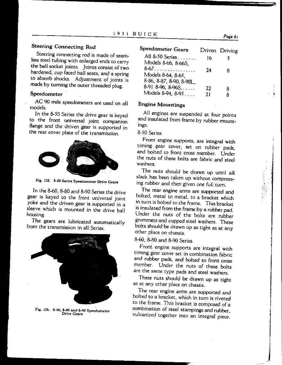
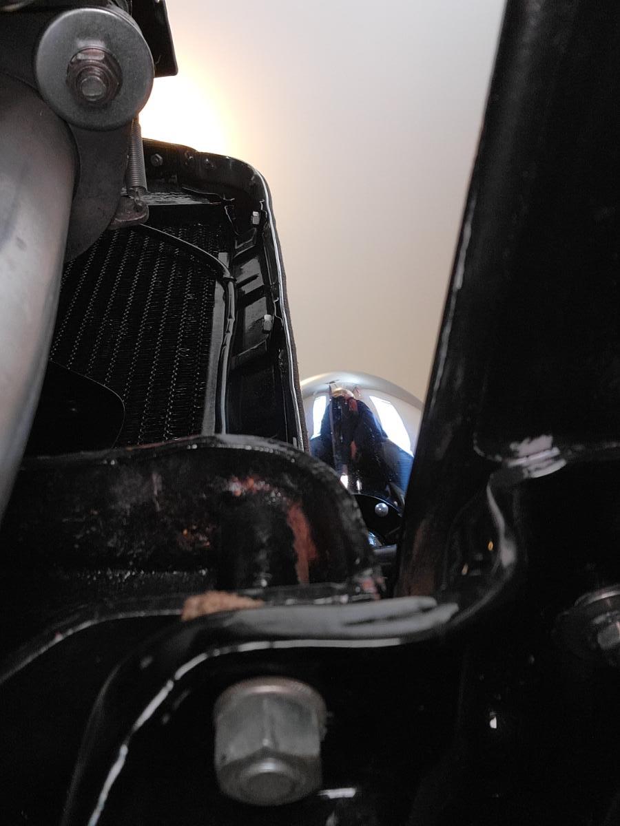
Hello to all; I started a thread a few weeks ago to get some input on fixing another sorting problem for my car, engine related vibration, not extreme vibration, but annoying, knowing the original build quality of the car. That thread turned out to be very productive. In my ignorance of how mechanical things actually work I suspected the entire source of this vibration was the fact when the engine was overhauled the original iron pistons were replaced with considerably lighter aluminum pistons. How did I know this? I bought a cheap bore scope and went looking in the cylinders through the spark plug holes, and there they were, bright shiny aluminum pistons. Where I really mis-led myself was I assumed changing piston weight should have resulted in re-balance of the rotating assembly which I suspected had not been done. Brian Heil from the Flint chapter of the Buick Club chimed in and said as long as ALL the pistons were changed and assuming they all weighed the same as on another, the engine would still be in balance. That was a watershed revelation for me because It meant I didn't have to fear pulling the engine, disassembling and balancing it again. Other suggestions related to rotating assembly problems such as a defective crankshaft torsional balancer I ruled out because A- the weight stack components of the balancer were factory welded, and there is no rubber in its construction, and B- the engine runs very quietly, free of major mechanical noise. Other suggestions were engine tuning related such as cylinder misfire caused by low compression, carburetion, ignition synchronization or timing, bad wiring, fouled plug, etc. The engine timing has been verified including point synchronization. The carburetor was overhauled with a Carburetor Shop overhaul kit and reproduction venturi blocks from 32Buick67. The engine really runs well, idles right down, pulls well under load, it just seemed to vibrate enough to be annoying. But there was one more suggestion, it could be engine mounts. If it finally turns out to be specifically rear engine mounts, that would still be a major job to fix. The rear engine mounts are rubber-over-steel vulcanized units and they are riveted to the frame rails. I'm hoping they are not the problem. Whether the rear engine mounts are or are not a problem I finally discovered the front engine mount WERE a problem. Careful reading of the 1931 Buick Specifications and Adjustments manual revealed front mounts are intended to isolate engine vibration from being transmitted to the chassis by composite pads made of canvas reinforced rubber. There should have been a pad between the timing cover of the engine and the frame bracket the front corners of the engine are bolted to. The 1/2"-13 thread grade 5 bolts pass thru tubular reinforcements in the timing cover, then a composite pad, then thru the chassis bracket, then through an identical composite pad, then flat washer, lock washer and nuts. What I discovered was the 1/2" bolts passed through the timing cover, then through a very tired looking pad with no sign of rubber, then through the chassis bracket with flat just a lock washer, no insulating pad, no flat washer to distribute the load. I decided I might have stumbled onto the source of the vibration and set about figuring out how to fix it. The hardest part of the job really, was trying to find replacement reinforced rubber pads ready to go or at least finding appropriate material to make new pads from. I checked with Bob's Automobilia, Steele Rubber, Cars, and Straight Eight Classic Car Parts and they had nothing. On E-bay I discovered a seller who was selling round rubber washer insulators for 1933-up Buick for just $75/pr. That would have cost $150 for 4, 2 for engine to chassis, 2 for under the chassis bracket. I checked McMaster-Carr and they had lots of 6" x 6" x 1/4" thick rubber sheet for $110-up depending on material spec. Finally, I discovered a seller on E-Bay who sold 2" x 2" x 5/16" thick cloth reinforce rubber pads salvaged from aircraft tires for $7.95 for 4pcs. All that was missing was the 1/2" bolt hole in the middle of the pads. I ordered a set of these pads and got them in 4 days. I made a drill press fixture to hold the rubber pads to the drill press table and drilled them with a 1/2" wood cutting Forstner bit. The last part of the job was installing my new insulators. Buick warns the rear mount attaching bolts at the flywheel housing must be loosened before the engine can be lifted or moved. Failure to do so will damage the rear mounts causing them to transmit engine vibration to the chassis. I dutifully loosened all 8 rear mount bolts before I attempted to raise the front of the engine. After removing the front engine mount bolts I jacked the front of the engine up less than 1" with the end of a piece of 1" x 6" ash lumber lifting at the mounting flange of the oil pan. this allowed me remove the 2 old, tired insulator pads which were installed between the timing cover and the chassis bracket and replace them with 2 of my new pads. Then I let the engine down and after some trimming, installed 2 more new insulators under the chassis bracket and installed a heavy-duty flat washer, then a lock washer and the nut on each side of the car. The last step was re-tightening the 8 rear mount bolts. I won't know if I fixed anything until spring when I can drive the car again. The engine mount/vibration issue is one major sorting project I won't have results of until spring, the other is whether or not my gas gauge works after removing the tank, replacing the hydrostatic sending unit and rebuilding the instrument panel gauge. I have my fingers crossed on that one for sure. The last sorting project I will work on in the spring is setting front end toe. I bought a toe-gauge but the car has to be on the ground for that adjustment. It is still on jack stands and before I take it down I will loosen the tie rod clamps and get the barrels turning. Dave The first 3 pictures are scans of the engine mount description in the 1931 Buick Specifications and Adjustment manuals. My car is a 60 series car so sections on 60/80/90 series apply. The short 60/80/90 paragraph bottom right of Page 81 describes pad material and states there should be pads between timing cover and chassis with a second pad under the chassis bracket. Under Engine replacement on Page 82 importance of loosening rear engine mounts is discussed. Page 83 discusses installation of shims at the rear engine mount locations. This is a picture of the left front engine mount with the original pad sticking out of mount between the timing cover and the top of the chassis bracket. Note there is no insulation between bolt head and timing cover. Here is what I found UNDER the chassis bracket. Note the picture is still of the left front but the image is transposed, left to right, because I used the selfie setting on the camera for this picture Lookin at the bottom of the picture, all there was was the nut and a lock washer, no insulating pad. So now you have metal to metal bolt contact at the top of the timing cover transmitting vibration from the engine thru the bolt, lock washer and nut directly to the chassis at the engine mount frame bracket. this is the bottom of the right front engine mount, again transposed left to right, again no rubber insulator between mounting bolt and frame. The original and only insulators that were in the car were the bottom 2 tired looking examples. I made this snappy drill fixture to allow me to securely anchor the rubber insulator to the drill press table. A pad is installed in the center ply of the fixture. Then the fixture is assembled to the drill press table so the drill press operator doesn't wind up tangled in an angry drill. The 1/2" Forstner bid did a pretty clean cutting job. 1 down, 3 to go... Here is a picture of a new pad installed between the timing cover and chassis bracket. This picture is not transposed and shows left front mounting bolt with insulator pad and flat washer added. Now the metal-to-metal connection between mounting bolt and frame is interrupted so engine vibration no longer is transmitted directly to the chassis through the mounting bolt. Right side mount with new pad. Insulator, flat washer, lock washer, nut under the right chassis bracket, metal to metal vibration path interrupted.


-
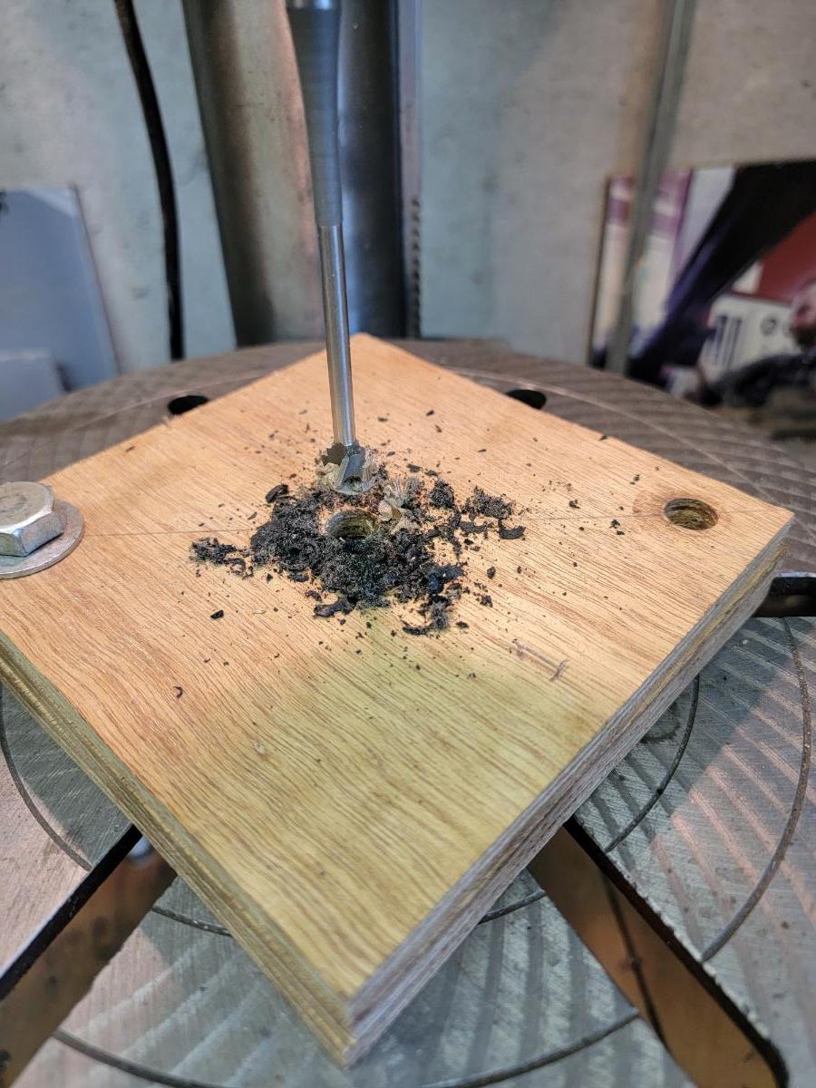
I tried a bunch of different sources for fabric reinforced material to make new insulator pads from for my front engine mounts and finally discovered a seller on E-bay that sells 5/16" thick 2" x2" pieces of salvaged aircraft tire material. 4 piece lots were priced just under 8 bucks. What was missing was the required 1/2" hole in the center of the pads. I made a plywood holding fixture made of 3 6" x 6" 3/8" thick plywood. Top layer had a 1/2" hole that is centered over a 2" x 2" window in the second layer of plywood. The third layer serves as a support pad. I drilled 2 more holes on a diagonal center line about 1" from 2 diagonally opposite corners to allow the fixture to be thru-bolted to my drill press table. I successfully drilled 1/2" holes in the 4 insulator pads, cleanly cut, with a wood working bit. I will post an update with pictures after installation in the car. Dave Pictured are the 4 fabric reinforced pads I found on E-Bay along with a holding fixture I made to safely and accurately drill the 1/2" bolt holes in the center of each pad. With the holding fixture loaded with a rubber pad and bolted to the drill press I got nice neat holes centered accurately and drilled with my hands safely away from the action.


- 51 replies
-
- 10
-

-
The cast iron won't care as long as after the coolant boils off and things get really hot you don't cool it off suddenly. If we are talking non-pressurized cooling systems 21 is too hot because the coolant will boil off. At sea level water boils at 212degF, every PSI you can raise the pressure of the cooling system gives you another 3degF before coolant boils. Bearings won't fail at 212 but if coolant is 212 and you have been running for awhile under load oil temp will be a lot higher than 212. I'm not sure what critical oil temperature is so won't opine on how hot is too hot.
-
McMaster Carr was one of many sources I checked out. They didn't have anything. All their reinforced rubber washers are 0.110-0.140 thick. That's pretty thin for isolating a heavy engine from the frame mounts.
-
Ok guys; I may have finally found a good bet on the source of vibration in my car and it turns out to be front engine mounts. The 1931 Buick Specs and Adjustments clearly states engine alignment must be correct when installing the engine in the chassis. For front mounts that means with rear mounts assembled with bolts loose, front of engine should be aligned so front engine mount bolts drop through the holes (which are actually tubes welded in place) then drop loosely thru the chassis bracket holes. I wasn't around when the engine was reinstalled in my car so before I do anything I will loosen the rear mount bolts, which the Specs and Adjustments manual states must be loose until front mounting holes are lined up, then I will make sure front mounting holes are lined up correctly. Misalignment of front mounts COULD BE an issue, but it's not the whole story. What SURELY IS an issue is front bolts are supposed to pass thru the timing cover and there should be an insulator pad made of rubber and canvas between the timing cover lugs and the chassis bracket at the bolt holes, then below the chassis bracket there should be an identical rubber and canvas pad, then a flat washer, then the nut and lock washer. Umm- we have some missing parts according to the following pictures. I made this discovery yesterday and it looks like there is some kind of canvas pad (no sign of rubber) between timing cover lugs and chassis brackets but pictures under the chassis bracket show only a nut and lock washer present. So now we have a direct path for engine vibration to be transferred directly to the chassis because the head of the bolt is in hard contact with the timing cover and nut and washer under the chassis bracket are in hard contact with the chassis. I spent hours yesterday on the internet trying to locate suitable material to make anti-vibration cushion pads from. No one seems to have anything in the way of pads made of rubber and canvas or suitable material to make them from. Does anyone know of a source? One idea I had was to make pads from canvas reinforced rubber tail pipe hanger strap which is a layer of rubber, layer of canvas and another layer of rubber. Another way might be to use non-metallic woven brake lining with hard rubber washers. If anyone has a better idea or knows who sells something like this, I would really appreciate hearing from you. PS: Edinmass- if you see this, I should have listened to you a long time ago when I first started talking about this issue. You told me I should look into engine mounts as a source. My head get harder with my ancient age.... Thanks Dave Read Engine Mountings from pages 81-83 the 31 Specs and Adjustments manual for 8-60, 8-80 and 8-90 series below. May car is an 8-60. This is the left front engine mount bolt, metal to metal contact from head of bolt to timing cover. You can see the edge of an insulator pad sticking out of the space between the bottom of the timing cover and the chassis bracket. It looks lik canvas only, no sign of rubber. Below the chassis bracket where the Specs and Adjustment manual says there should be an identical insulator pad and a flat washer to insulate the bolt from the chassis bracket there is only the nut and a lock washer, so now, there is a path for engine vibration to travel from the engine to the chassis. The image is reversed because in order to get into the small space under the chassis bracket the picture was taken with the Selfie camera setting. That's the exhaust head pipe flange in the upper left corner of the picture. Here is the right front mount. Bolt head is again in solid contact with the timing cover. Beneath the chassis bracket in a reverse image is the nut and lock washer, no insulator or flat washer in sight.


-
Paul- not sure what type of tank sender was used for 1924-5 Buick, suspect it is hydrostatic with King Seeley instrument panel gauge but just not sure. In any event take pictures of what you have and talk to the folks at KM Lifestyle in Massachusetts. They make various types of tank gauge units for early cars. I bought a reproduction Atwater Kent hydrostatic unit for my 31 Buick from them and am anxiously awaiting spring to try it out. KM Lifestyle Mfg. Fuel Senders Auburn, Buick, Cadillac,Chevrolet, Chrysler, De Soto, Dodge, Franklin Plymouth,Pierce Arrow,Studebaker (mykmlifestyle.com)


-
The vibration WILL change if I push the clutch in UNLESS I hold engine RPM steady. At engine idle, there is little or no vibration detectable. Now, I had thought about just running the revs up in the garage in neutral and pushing the clutch while holding engine rpm to see if that affects vibration or stopping the car on the street and with clutch depressed in low gear revving the engine up to see what I get. If by any stretch of the imagination doing so resulted in vibration going away that would mean clutch driven plate, IE friction plate splined to the input shaft of the trans, has an issue. Clutch housing and pressure plate would still rotate flywheel speed and assuming no difference in vibration, housing and pressure plate or even the flywheel, could be the culprit I suppose. The pressure plate would be least likely to cause vibration unless it was missing a shock dampening spring or a sizeable chunk of lining material. Clutch housing and pressure plate are always at engine rpm and are much heavier components, more likely to cause noticeable vibration.


