


Car guy in Virginia
-
Posts
87 -
Joined
-
Last visited
Content Type
Forums
Gallery
Events
Everything posted by Car guy in Virginia
-
First, thanks. Another long day, but most productive, due to all the help so far. So ... it appears there are 3 main (Ign V pin-supplied) power feed paths from the RBO. A thin trace to the ignitor circuit monitors + a thick trace that routes to all chips for their power feed (including for the ignitor power switching controllers) + a thick trace that feeds into two separate parallel sub-paths for the two taller 35V 470 uF caps - 1 sub-path per cap. The two 470 uF caps appear - at the moment - to be supplying the current for the two front air bag ignitors. Given the 3rd path (with its two sub-paths) and considering the capacitors' sizes and roles, electrically does this point more toward their in-path 2-stripe devices being chokes (inductors) or the high watt resistors? More later too, when I can get above the water line. submerged. Thanks. P.S. Oh, and I figured out one of the smaller 220 uF caps as well.
-
Sorry late getting back again. Thanks for the continuing support/help! The two B best-guess diodes are interfacing with a Siemens V1-1 (VB934333) 28-pin chip. The VB sequence appears to change from board to board, but the V1-1 doesn't. Do you have access to datasheets (or know anyone who does)? Haven't been able to find the Siemens V1-! sheet. Also, CMD PRN258 93352015. And, Philips UAA1280T. Any ideas how to track down these datasheets or spec sheets? Against the orange, the stripes are hard to know for sure. But, they appear to be tan, but there is no tan on the color chart web site provided. So, brown would seem to be the next closest match, yes. Does F's 100 ohms make sense circuitry-wise considering A's tantalum 333 16V cap and B's diode, thick-tracing to the Siemens chip? This reminds me to ask about another part N, in the attached image. On L, given that the RBO isn't providing the 5V for the chips, how does the chokes vs. high watt resistors possibilities resolve? And, how is the Alt's 14V getting stepped down to the 5V? The pic above (right image) shows the sequence (with the main connector in the fore where the ign V enters, leading to the RBO, then the Ls, then the chips beyond. The # on the underside of the circuit board (where the DE logo is) reads 39.21.02. All of the boards have this same #.

-
Bloo, huge thanks again. In sync on everything except B, F, and L. Incidentally, confirmed your insights on the unpopulated grids - mapped all those connections ... and lack thereof, which yielded the confirmation. And, actually there were 4 unpopulated pads (some smaller ones). Which is one of the reasons I'm so late getting back ... So, here are close-ups of B and F and L, and here is the datasheet for the RBO. Thoughts now on what B is ... and F ... and L is ... and whether the RBO is or is not the 5V regulator, given the (ignition V-to-)RBO-to-L-to-chips sequence? Incidentally, can't recall if I mentioned, but the chip that processes the serial I/O to/from the data port does not go through the RBO. It only goes through one of the Ls and then one of the white/tan/white interference suppression capacitors - all of which can be seen in the last image (bottom right). In fact, that cap is the largest of those types on the board. And on this thought, there are 4 large caps on the board - 2 35V 220 uF and 2 35V 470 uF. Do you think each one is for a given ignitor? 2 small ones for the pretensioners and 2 larger ones for the air bags? The pretensioners fire with 1.0A for 2mS and the air bags 1.75As for 2mS. Or, given your comment, do you think they are used in pairs (in series) - one pair for the pretensioners and the other pair for the bags? https://www.st.com/resource/en/datasheet/rbo40.pdf Larry, thanks for the DE. That surprises me though, being this is an early Hyundai module, which I thought Siemens had built. Siemens' # is on the module cover as the part #. Can you reconcile this/educate me? And, yes, the car is being AACA restored. 37, thanks for the diodes insight. Others, no worries. None of those things are being done.


-
Wow, fantastic! A. has an orange top stripe, yellow body, the letters "S+M", the #s 336 and 16V, and then small letters LH and small # 79. So 33,000,000 pFs? Or 33milliFs (see my pF/uF/mFcomment on E below)? And why 16V? What is the significance of 16V here? [I think the destination chip on the circuit board to/from A "may" be the circuit board's serial I/O chip communicating the board's related air bag statuses.) Okay, so here's the A routing. This tantalum cap traces from its + marked orange top stripe end outward to both one of the 2 smaller-height vertical capacitors on the circuit board [each being 35V 220 uF - which I'm presuming are 1 per seat belt pretensioner ignitor circuit ... (there also are 2 taller-height 35V 470 uF caps presumably 1 per front air bag ignitor circuit)] and to "under the middle" of the "little barrel" B (when you say B is a choke, this means inductor or coil, right?) and then to F (whose "resistor" colors white, black, white, gold would be an enormous 90 * 10 to the 9th ... 90B ohms, so not a resistor then, right?, so then F is a coil/inductor/choke, right?) and then from F to the given chip's pin. So, A (capacitor) to B (what???) to F (coil/inductor/choke) to chip pin. And, then the very next pin on that chip has its trace going back to the other end of F and then to the negative end of B. Now B (the little barrel) has orange on one end (+) and green on the other end (-) with a tiny gap in between where it looks like you can see into the barrel (aluminum-like). So, when A traces to under the middle of B, is the trace conducting to a contact point in B's middle in between the orange and green - and if so what is happening there ... given now what you think B may be? Why the A to B-middle contact? And, in revisiting A & B and the sequence, what do you think the functional A-B-F-chip sequence is doing? What is the electrical effect? Taking max 16V-capacitance (A) and choking it (B) and then choking it again (F) before entering the chip? The trace from A to B to F to the chip is thick (not thin like most of the board's other smaller circuits). The trace back from the chip-F-B (negative) is slightly less thick, but still thicker than the board's other thinner traces. B - really curious as to what it is ... especially if its upstream trace F is a choke/inductor/coil. Two chokes/coils/inductors in a row - B and F? Education please. C, D, & I - I was thinking these were noise suppression capacitors. And, yes, I has one for each circuit - pin - coming and going into and out from the main connector. I know the main MCU is supposed to have a noise suppression device right next to its 5V supply, and indeed it does ... one of these, just like C. And, each one has white ends and a tan (or gray) middle, and no # (that can be seen). All the Cs on the board are the same small size, and there's 1 D (larger size) and 1 other one slightly larger still, and 1 smaller one than the various Cs. E any chance this is a capacitor that results in a specific clock or frequency (oscillator) for the chip it connects to? E - on one of its pins - has a thick trace going into the chip - whose datasheet I can't find but believe to be 4 MOSFETs (do you have access to datasheets?) - and has a thinner trace coming back (on the next chip pin over) to its (E's) other pin. E wouldn't the Vishay (huge thanks for that logo company name!) "220,000 pF (picofarads)" be 220 uF (rather than .220 uF)? pF=.000,000,001 and uF=.000,001 and mF=.001, right? F how do I interpret the colors of the coil/inductor/choke (since it appears to too high to be a resistor)? Or do you think they may be capacitors after all? No #s, just the color stripes. G these letters are extremely hard to see (on that single teenist chip), even with a magnifier. But, they appear to be "1Fp" (yes, 1Fp, not 1pF) followed by two sideways/perpendicular letters where the first letter I can't make out and the second letter may be a G. Maybe QG (or maybe QC). Any additional insight into this teeny chip now? H in sync (resistors). J I love your thoughts on space not needed for the given board! the 2 rows of equally spaced 7 pins perfectly fits a 14-pin chip now that I focus in on that central part of the J grid. But I was puzzled to say the least when, for example, I traced a pin from the air bag controller chip to one of the super narrow tiny "slit" solders in the J grid - where that slit solder doesn't connect to anything ... but ... I hadn't mapped out ALL those grid lines ... K fascinating that you mentioned cut to calibrate something. The on-circuit-board accelerometer comes with a calibration code bar-code-stamped on it to make it easy to "automatically calibrate the sensor during assembly." L very interesting you spotted the device to the right. It's a Reverse battery and overvoltage protection chip, whose datasheet I have, and have gone through, specifically looking for the 5V step-down. But, the datasheet didn't mention anything about any V step-down. Never found anything indicating 5V. (It's rated 40A and 40V.) So, back to the 3 Ls ... and the 5V for the board's chips/circuitry. Tracing shows ignition V input pin (from the main connector) going to the RBO and then to an F choke/inductor/coil (or cap, pending your answer to F above) and then to these L chokes?/inductors?/coils ... and then to the chips. So, what am I missing in regard which device(s) are stepping down and regulating the V to the 5 needed by the MCU (and others)? Is the RBO still doing it, even though it doesn't so indicate in its documentation?? Also, do you recognize the logo in the attached picture? What company was this? Thanks!

-
A through L (and ratings where applicable).


-
I need to know what some specific devices are on an early air bag computer module. On the actual circuit board. Someone with electronics circuit board experience or expertise. Thanks.
-
Is there someone in the club with experience or who works professionally with automobile circuit boards. Or does any club member know someone who does? Thanks.
-
Still seeking this OEM Nissan part (in the title and as shown in post #1). 16860-33M17 VCM air filter assy Appreciate any/all leads.
-
WOW 37, if we all were together and I could lay out all the data and videos and pictures and schematics across a couple tables, I (we) could point to everything you just mentioned. Indeed, as I read your additional explanation, I could see each sentence's point in the traces and schematics. There, right there it is, there, right there is that, there, right when it's supposed to be, there, see when that peaks, there, see where those diverge, there, see how that is now gone and this is continuing, et al. I think at one juncture (during the posting) I had raised a series of questions focused on can we point to when ..., and we can. You're amazing. Glad Bloo and you had lunch ... : - ) and sorry I missed it ... Much thanks for getting back. With respect.
-
Fantastic explanation. All of it. Thanks! I think it was Bloo who suggested looking at the current trace. Overlaying that data with both your explanation and all the AC scope data [and actually also all the other DC scope data, where the AC and DC perfectly align right up to the point of AC ripple ramp down and DC 14.xx V continuation (fascinating to see that point of divergence)] reveals that the AC ripple, the 1.x Vs caught simultaneously by the scope and multimeter, after leaving START (to ON), is when your criteria are met (on the various cars). And, once walking through the Darlington and Zener again (something took me back into those parts of the alternators and those portions of the schematics), the (alternators' internal electrical) sequences firmed up. So, we're there. And, this closes the loose ends for me from the schematics. Much thanks for that. And, I'll leave you with this, as it's just too funny ... the Darlington B-E V (Vbe) would appear to be 1.3 ... which is right around the 1.368 AC ripple Vs. What a great way to end the project. :- ) Thanks.
-
Hey Ben. I recall your assistance from an earlier post a few years back (I think). I had most of it figured out, but was questioning the scope's initial AC (thanks 37) -2.75Vs, apparent AC humps on the rises toward 0, initial small positive AC (small hump), and the 1.x AC ramp ups. This led me to question how the diodes could be outputting anything negative AC-wise (all the alternators are fine). That sent me deep into the alternators electrical schematics, to see if there was a sequence explanation therein. I could fine none. All the schematic sequences (not an easy task) revealed no explanation. What I was missing - that bloo caught (huge thanks!) - was that the 1.x AC Vs were the starting loading ripple. Deep in my subconscious was the threshold usually used for excessive AC ripple ... which none of the cars had demonstrated throughout all the normal accessories loads measurements. Indeed, all the normal accessories loads ripple measurements were well below threshold, and the patterns looked great - exemplars. Once bloo said what he did, the subconscious rose right up to consciousness. The answer was instantly manifest. And, I also would say to bear in mind that to collect comparable START scope data along with multimeter data while simultaneously video recording the results across various cars took days and repeated setup and teardown work, not to mention all the comparison work that ensued. So, yeah, I needed help ... but, also I understand everything everyone has said, except for the few clarifying questions I have posed back.
-
This helps. Thanks. So, to clarify, timing- and sequence-wise, looking back at the 1st picture, is your reference to the pickup the rise toward 0 V, the slight positive immediately thereafter (the small hump), or only the 1.x V ramp up (the large hump)? (The 1.x in this case was 1.386V; it was on the picture.) And, during the starter's execution - with the alternator rotating (during those 1.6 seconds), is the alternator initially outputting during the rise toward 0 V, during the slight positive thereafter, or only during the 1.x V ramp up? Or, only during the latter two (and not the first)? Understanding this would wrap up a lot of schematic loose-ends. Thanks.
-
Larry, thank you, indeed. This is exactly the type of clarification and confirmation that syncs with all the data collected and syncs with the analyses of the various alternators' internal electrical schematics. Thank you for taking the time to write it. And, thank you for the being the first person to respond on the post. I had submitted it Sat., but after 80 or so reads, no one had responded by Mon evening. And, yes, the battery (from these scope pictures) is a good one, so you correctly determined that as well.
-
Consistent with your thought, the cars with the oldest batteries had the most 1.x A/C V and those with the newest batteries had the least 1.x A/C V (now that I think all those through). Also, one of the carbureted cars had sat for a couple days in high ambient heat, and the float bowl vacuum-lost some fuel. Guess what its 1.x A/C V was when trying to start? Almost as high as the oldest battery car (now that I think that through). So, thanks for this thought. All part of understanding and knowing the cars in the fleet. I've electrically baselined nearly all the systems across them. Just hadn't done A/C V from START before ... on the scope ... Thanks.
-
Excellent! So, you are answering the original first question then: the 1.x A/C V is the increased-loaded alternators responding ripple-wise proportionately to the drawn starting current which is then (during the 1.x A/C V duration ramp up and ramp down) being replaced? And, this further explains why the 1.x A/C V only happens once - and only at the end of START to ON ... and not before then nor again when running. And, this also explains the slight variation in the 1.x across all the cars. And, this also explains all the signal patterns being the same across all the cars. What's also interesting pre-charge-wise is being able to see the starter V drop and V recovery (as the starter overcomes the engine's inertia) on the D/C V scope pictures and the A/C V drop negative and negative V recovery toward 0 as the alternator simultaneously begins rotating. Overlaying those scope pictures was cool, to say the least. I actually was glad you mentioned the spike, because, if you look closely at the 1st scope picture, the 1.x A/C V ramp up actually begins vertical ... and rounds from there (rounds up and rounds down). Though, now, it appears that vertical is the beginning of the current replacement. Notice how it gets half way up the 1.x A/C V ripple at the immediate beginning of the hump. Yes, but - for clarification - are you thinking the A/C V negative rise toward 0 (look closely at those initial humps in the 1st picture) is the alternator then charging (beginning its charging) ... or are you thinking the initial positive small hump A/C V is the alternator then charging ... or are you thinking the 1.x ramp ups and ramp downs are the alternator then charging ... or are you thinking all 3 are the alternator charging-away? This is a loaded question, but I don't want to bias your thinking/answer. This is interesting also because, initially, the regulated V appears to be below the zener diodes' threshold [given the -2.75 A/C V (drop)], so the regulation occurs through the combination of the path through the field coil and also not through the field coil (the 2 inputs, at this juncture, to the first transistor). One of the sequences ... Fascinating engineering. Yes, I have that data ... though in another form ... and it does agree (now that I put thought to that set), as the current usually jumps to 13As and immediately ramps down to 9, 7, 5, 3, and lingers around 1.8ish As. Huge thanks Bloo!
-
Yes, I'm with you on this. No PWM and no BCM and no ECU-controlled alternators in the fleet (of cars being assessed), as it happens. Yes, this is part of the differing sequences I was referring to in a couple of the posts; so am in sync on this also. Glad you mentioned both points. Oh, and for those following this, the reason I had asked Larry and Bloo if they had seen scope A/C V signals from START is that other technicians with whom I have spoken have said they only have looked at A/C V once the cars are running. Thanks.
-
Yes, earlier I had posted that I had all the corresponding DC V pictures and measurements as well. And, indeed, the AC and DC signal patterns (not voltages) align seemingly perfectly ... until the 1.x A/C V ramp down ... at that point, the DC continues high (14.xx). So, thanks, and I'm glad you posted and posted this very thing. So, given your insight on this part, can you explain IF the scope's A/C signal IS or IS NOT actually A/C signal ... and can you explain if it IS or IS NOT alternator A/C output? These both are critical. And, can you explain why the 1.x A/C ramping down occurs when the DC already is continuing high (steady 14.xx)? Thanks.
-
It was part of a larger process to measure (and determine) and baseline the health of all the alternators (across the fleet). When I got to the A/C part of the process, the (A/C) ripple was measured, with and without loads, and during START and ON. Everything measured as expected (and was fine), except I was surprised to see the A/C immediate negative drop (to -2.75V), followed by immediate A/C rise toward 0V, followed by the slight initial positive A/C V, followed by the (higher) 1.x A/C ramp up and decline just before the A/C V stabilized at 0 from then on. And, I especially was surprised to see the exact same sequence of A/C events across every car measured. Plus, I was surprised because I was expecting the rectifier to cancel out any negative A/C V, and began wondering why the scope was showing negative A/C. This raised a question about how it could be that the alternators' negative A/C gets out(put) during START. It seems that it should not. But, the scope showed (essentially) the same negative A/C V on every car measured. It seems the diodes should prevent this very thing? Then, once the A/C V went positive, that made sense [from a couple different perspectives, release of the starter (release of that current draw), activation of the field coil, internal capacitor supplying/smoothing initial output V, etc]. But, then when the A/C V ramped up to 1.x and ramped down (to 0), then I was lost in the sequences ... and, again, there are different sequences internally in the alternators ... so, given the different possible sequences, which of the devices in the alternators were driving the ramp ups and which of the devices were driving the ramp downs ... and why. And ... were they the same devices doing both? Or ... was none of the A/C on the scope actually A/C? Was it actually A/C impact by the D/C starter draw down and recovery? And was part of it A/C impact by simultaneous field coil draw down (among other simultaneous current draws across the cars)? And, if so, when - along the signal path - did the scope A/C signal begin being actual A/C V. I have thought about this, but it remains unclear: is the immediate A/C V rise (from negative -2.75) toward 0 the field coil coming on (the signals there certainly appear A/C hump in nature) ... or is the initial positive A/C V the field coil coming on ... or is the 1.x A/C ramp up the field coil coming on ... or are all three of these the field coil coming on in fits and staggers (as the starter jerks the car/alternator over) .... ? I'll pose that question. And, I would ask in return ... On the 1st scope picture, can you point to when the field coil is coming on? Can you point to when the capacitor dumps? Can you point to when the zener diode (first) switches (on)? Can you point to when the zener diode possibly re-switches off? Can you point to when the battery excitation of the field coil ends and the alternator is self-driving the field coil? And, then there's the question of what explains the 1.x A/C V ramp down (to 0). Because certainly by then the battery excitation of the field coil is done, and the alternator is self-driving the field coil. So, which devices are ramping the 1.x down ... and why? Thanks.
-
Larry, Bloo, can I take it you have not seen alternator o'scope signals before, from START? When I posted the o'scope information and worked up the material onto the pictures, I was trying to simplify all the data to direct the question. The pictures and work took days to collect and to synthesize. I also have all the parallel DC V o'scope pictures, as well as all the corresponding multi-meter A/C and D/C V data and pictures, as well as all the A/C loads data and pictures. Several weeks invested, in toto. Last piece of the puzzle is the explanation of the 1.x A/C V ramp up and down. Thanks.
-
Yes, the alternators bootstrap (to use your wording). The battery supplies the excitation when ignition is START or ON (but only ON, before the alternators are running). Yes, the excitation occurs in/for the inner coils for the magnets; then when the magnets are rotating, they are inducing the current into the outer coils (stator). The control of the inner coils is through the internal Vreg (a multiple nested transistor, multiple resistor, and multiple diode regulator). The capacitor is inside the alternators but outside the Vreg. The dash light is not involved in exciting the field (inner coils), as it happens. Thanks.
-
Yes, A/C voltage. Yes, from the very START of the cars. Yes, the 2nd and 3rd pics are the (uninterrupted) continuation from the 1st pic. Thus, the A/C V is being shown in its entirety from the very START through ON through the point where the alternator is now charging the battery and supplying the cars' electricity. It is measured at bat (+) and bat (-), which are the same as the alternators' (+) and case ground. What I'm asking is: why is the o'scope showing 1.x A/C V at the end of the START/ON process - and only then ... and not again ... and not before then; and where is the 1.x A/C V coming from ... what inside the alternators is doing this ... and, in what sequence inside the alternators (where exactly in the sequence). I think the sequence is everything - it matters, especially since there are different sequences of execution inside. The alternators begin executing one way, but then transition to executing another way. I have walked through the sequences, but can't explain the 1.x A/C V rise and decline. Thanks.
-
Anyone?
-
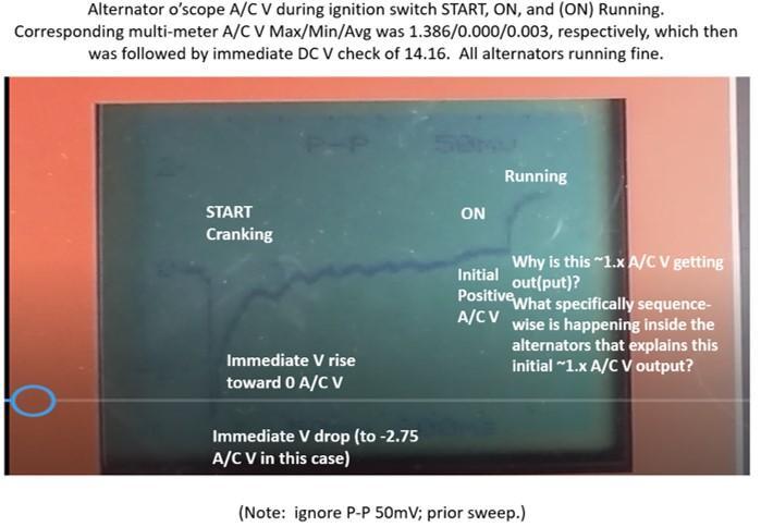
First of two sets of questions: Why do alternators output ~1.x A/C Vs at the end of ignition STARTing, just after leaving the ignition switch START position and being in the ON position ... that is, when initially running? What, specifically sequence-wise, is happening inside the alternators that explains the initial ~1.x A/C Vs getting out(put)? I'm particularly interested in the exact sequence of explanation (considering the alternators are being turned and are having their field coils energized, and are having their V regulation to the brushes and slip rings and rotors, and their rotating magnets are inducing the current into the 3 stator coil windings, with the rectifier's diodes converting the A/C into DC for output.) Attached is a set of three A/C V o'scope pictures. The first pic shows what happens during Start: immediate V drop (in this case to -2.75 V), then immediate V rise toward 0V, then slight rise to positive V (the initial small hump). The initial hump is when the ign sw has changed from START to ON. At the end of the first pic, the alternators are running (now in the ignition ON position). And, this is where there is the graceful, larger 1.x A/C V ramp-up ... the second/main hump. In this case, 1.386 A/C Vs. The second pic shows where this 1.x A/C V promptly ramps down (on the far left) and then shows how the alternators' A/C V stabilizes around 0 V (rest of the pic). The third pic shows where the alternators' running A/C V remains around 0V. Second set of questions Or ... is there another explanation for the ~1.x A/C V ramp ups and ramp downs on the o'scope's A/C V readout - just after leaving START - while the corresponding multi-meter also indicates the same ~1.x A/C V (as the max)? Thanks.

-
Still seeking this OEM Nissan part (in the title and as shown in post #1). 16860-33M17 VCM air filter assy Appreciate any/all leads. Tried all the recommendations above (no success).
-
Seeking coil spring manufacturers
Car guy in Virginia replied to Car guy in Virginia's topic in General Discussion
Stengel Bros.


