


1912Minerva
-
Posts
87 -
Joined
-
Last visited
Content Type
Forums
Gallery
Events
Posts posted by 1912Minerva
-
-
To answer your question Jeff, yes the 3 screw in plugs are to allow for the uneven clutch spring tail. The end that touches the spring should have a radius machined into it to match the size of the spring. They will be all set at slightly different depths to match the tapering off of the spring coil end. I don't have a real good photo but have circled one of the screw in plugs on the attached photo.
Really enjoying watching the great work you are doing on your Hup.
Cheers, Andrew.

-
 1
1
-
-
Hi Tom,
Whats the plan for the damaged rear block? Or do you have another you can use? Good luck with the rebuild...
Regards,
Andrew.
-
Great video Phil. Nice to see another Torpedo! Hope you're well and keeping safe.
-
Wow, yes I totally agree - well done. The ad matches the photo so well!
-
Lexington of around 1921
-
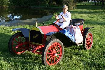
Our 1911 Torpedo bodied Model 20 at the National Veteran Car Rally in Bundaberg a few weeks ago. Cheers

-
2
-
-
Thanks for your advice Tinindian - appreciated.
Regards, Andrew.
-
Hi All,
Just wondering what people thought was a good cylinder compression reading (PSI) for a Model 20. I am getting 55 PSI on 1,2 & 3 and 25 on No.4. Obviously there is a problem with 4. I did a leak down test and it looks like rings are not seating.
Any thoughts appreciated.
Cheers, Andrew.
-
How did it go Simon?
-
Thanks for the photos Simon, that's given me some ideas. I have glued an oil seal outside the block and machined a small section of the flywheel away so that if fits with over the seal with some clearance as it spins. This seems to be working at the moment.
-
Yes, I think the back should be solid. I found I was getting a lot of oil leaking from there until I started filling the crank case to what I now think is the correct level. ie I was overfilling the crankcase.
Simon - does your car leak oil where the crankshaft comes out of the front of the engine where the flywheel is?
Cheers,
Andrew.
-
Congrats Buzz! Looks like a really nice car. I love the monocle windscreen. I think the Hup 20 compares pretty favourably with the Ford Model T (I've owned both). There is some good knowledge on this forum so if you have any questions when you start playing with it, someone should be able to help you out!
Regards,
Andrew.
-
Hi Simon and David,
Here are some photos I obtained from this forum when I was having a problem with my gearbox/clutch. My engine would slow down and stall when the clutch was depressed and on pull down, I found the thrust washers were missing. With the help of this forum, i had washers made up and now things work pretty well.
Cheers, Andrew.


-
Well done Phil - your car looks great! Did you have any issues with oil leaks? I find my Hup changes back to Low quite nicely using double clutching.
Cheers, Andrew.
-
Thanks Phil, David and Ken,
I need to drop the top of my petcock tube a bit more to get exactly 3/4 inch. Looking at the diagram Ken, the top of the petcock tube is exactly in line with where the top of the oil scoop (bottom of big end) would be at the bottom of the stroke. It is interesting that the end of the big end bolt and nut "blocks" the oil scoop. When putting my motor together we thought about that and worried that the bolt would form a "groove" in the oil and the immediately following oil scoop may be running in that groove and not picking up enough oil. So we reversed the big end bolts so the oil scoop has clear access to the oil. Probably worrying about nothing.
Cheers, Andrew.
-
Paul,
That is not bungee cord actually but something we in my part of Australia call "Paramatta Rope". It is woven blue and yellow rope with Blue and Yellow being the colours of the Paramatta Rugby League Club (Rugby League being a very popular sport on the eastern parts of Australia) - hence the name. It is very strong rope and while I would never advocate towing that load with only one or two points tied down, I would wager you could tow that a fair distance and it would never come off.
Bernie, I have been silently following many of your restorations on this forum and am looking forward to seeing you to go to work on the Triumph!
Cheers,
Andrew.
-
Hi All,
In between outings with the Hup Model 20 (only displays with minimal driving so far), I have been investigating the propensity of the car to throw so much oil out of the front of the crankcase so readily. While I understand that these cars have a tendency to do this, mine seems to take things to the extreme!
I took the camshaft plate / cover off the side of the crankcase to see what actual oil levels I had at the top of the petcock tubes. This was an interesting exercise that I should have done earlier. I found that the top of the petcock tubes were quite high in relation to the throw of the crankshaft and I suspect that the big ends were dragging through quite a bit of oil contributing to my problem and also probably causing some drag on the crankshaft as it made it's way through the oil bath.
The other interesting thing I discovered is that the capacity of the front crankcase compartment is much smaller than the rear crankcase compartment. ie. adding the same quantity in each will not result in the same level. The rear compartment has extra space under the crankshaft output.
I dropped the level of my petcock tubes by adding spacers where they screw into the bottom of the crankcase. This is an easy way of adjusting the height of the tubes inside the crankcase without making any irreversible cuts. I then jacked the car up as high as I could (to simulate going uphill) and checked to make sure the big ends would still scoop oil.
In case any one is interested, I have included some photos. In one you can see the void under the camshaft drive gear which results in more oil being required in the rear compartment.
Any thoughts or comments certainly appreciated.
Cheers,
Andrew/


-
Yes, in my experience with the Hup 20, to try and drive with your hands on the wheel as shown in that beautiful poster is asking for trouble....lots of trouble!
-
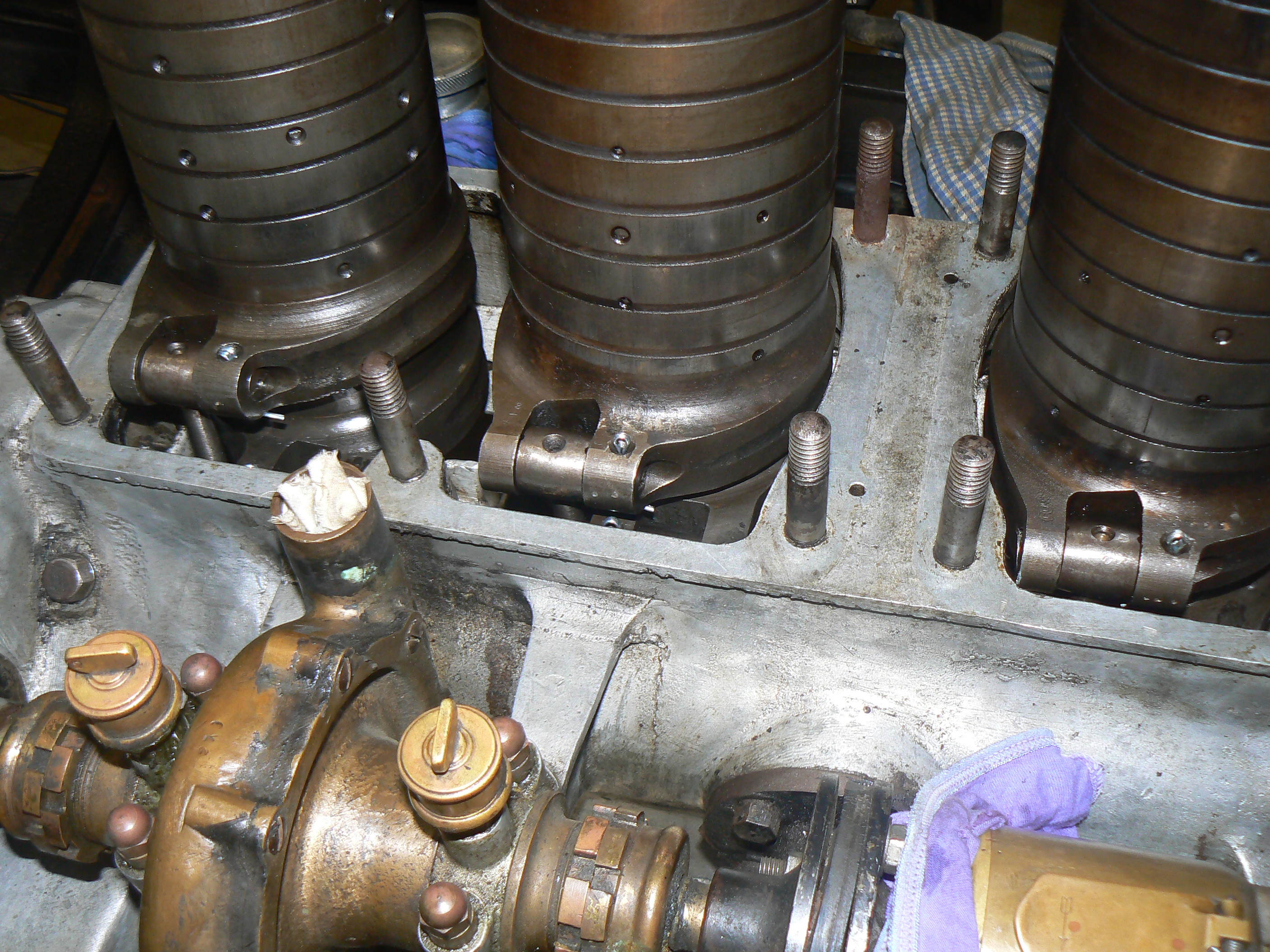
Hi Everyone,
I thought some here might be interested in some pics of my Minerva engine when I had it apart recently (and one of engine in the car).
Regards to all.
Andrew.


-
Hi All,
I too was very sorry to learn of Edgar's passing. He was enthusiastic and very supportive when I obtained my Hupmobile and provided information and advice. I am attaching a couple of low res pics that Edgar sent me of the trip he did in his Model 20 from Gympie to Sydney and return (for non Australian's that is a considerable distance) - I suspect he sent them to me by way of encouragement as to the potential reliability and drive-ability of these vehicles ( I love all his luggage strapped to the fender / mudguard!).
RIP Edgar and condolences to his friends and family.
Regards to all,
Andrew.

-
1
-
-
That's great news Phil!
I think if you blank off the bottom of the original manifold and then make up an adapter for the Holley NH that will give you the option of either carb without altering the manifold?
I run a Holley but my car came with the manifold cut off. I had to make an adapter to fit the Holley as the bolt holes are slightly different.
Cheers,
Andrew.
-
Hi Phil,
My torpedo hasn't got a generator yet but I have a photo of the generator mounted on the other torpedo here in Australia.
As you can see, the door would hit it. This car is a very early restoration (1950's). Looking closely at the photos, I think when rebuilding the body they didn't even put a door on the drivers side (can't see a hinge). This was the first car I ever drove (when about 10!) and also drove it 10 years ago. As most cars of that era are difficult to enter through the drivers side (due to brake and gear levers, spare tires etc.) I don't recall noticing that being unusual. This car also has what I believe to be an unusual feature for a torpedo in that the fuel (gas) cap protrudes through the body work so you don't have to lift the boot (trunk lid) to access.
Here is a photo of another car which is not a torpedo but is similar in terms of scuttle and doors (but it doesn't have the rounded back - just an exposed fuel tank like the runabouts). I'm not sure what this body type is called. Again generator is mounted on drivers side running board - this car may not have a drivers side door either - I can't tell.
The only period picture I have seen of a torpedo doesn't show any generator and I think the lighting shown may be electric?
Another period photo - not a torpedo but it does have doors and again has the tower style carbide generator. Interestingly the style of front guards the car has allows the generator to be mounted well forward of the door but the horn tubing looks like it would prevent the door opening.
Heres one without doors but showing a Prest-o-lite
I would love to see some detailed pics of your torpedo - there don't seem to be too many around.
Regards,
Andrew.


-
Following on from my last post, here is a photo of the petcocks on my car before I shortened them:

And, just for interest, is a picture of my car out and about:

-
Hi Max and all,
Thanks for the info. I have had minor success with seals between the flywheel and crankcase. One thing I have noticed is that the petcocks on my car were quite long, meaning I have been putting a lot of oil. See this thread:
I have cut the tubes on my petcocks back to what Karl's are in this photo (about 1.5 inches from bottom of thread) down from nearly 2 inches. This results in significantly less oil in the motor (I was putting in about 2 litres into the crankcase).
I'm sorry I missed the Singleton Rally but my car has just been leaking too much oil to properly enjoy.
We'll see how it goes with the shorter petcock tubes. Fingers crossed.
Cheers,
Andrew.


1911 hupmobile 20 restoration.
in Hupmobile
Posted
Actually, this photo (which I got from this forum - apologies to whomever posed it!) which shows the setup much better