Roger Zimmermann
-
Posts
3,130 -
Joined
-
Last visited
-
Days Won
24
Content Type
Forums
Gallery
Events
Everything posted by Roger Zimmermann
-

Roger's handcrafted 1:12 scale models
Roger Zimmermann replied to Roger Zimmermann's topic in Our Cars & Restoration Projects
Exactly! I still have to make the contacts and some hinges for the lid (I throw away some time ago a wood box with hinges...). A defective shaver with his electric cord could also be good for the output cable; I throw away 2 shavers some months ago! Of course, this box will be external.
-
Roger's handcrafted 1:12 scale models
Roger Zimmermann replied to Roger Zimmermann's topic in Our Cars & Restoration Projects
Thanks Rodney for your comments. Sorry for being late to answer: I was in vacation and somewhat lazy. Even in scale1:18, usually the molding are too thick, probably a necessity to have them strong enough. If I'm doing everything myself is to be sure that the element will fit. I would have been glad to find a side window mechanism less cumbersome that what I finally created. As I hate to search elusive elements, I prefer to do them myself. As you can see, I bought the electric motors! My models are rendered as like they are in a show room: no dirt, no rust, clean! However, I can understand you point of view... After the usual summer vacation, I’m back. I did however something during these 3 weeks next to cut vegetables: I ordered some decals for the generator, A/C compressor and other ones. They were in the mail when I got back home; they look good! With a remaining wine case, I did a small box in relation to the model. Do you know for what it’s good? The answer tomorrow!

-
'55 Hydramatic fluid leak at speedometer cable
Roger Zimmermann replied to Summershandy's topic in Technical
Sure a 1955 transmission is not the same as '56 to '63 Hydramatics. However, I overhauled about 25 second generation Hydramatic transmissions and never sew a seal at that place. My own cars are leaking some oil here too; I believe it's normal until somebody can tell mo how to avoid it. -
How do you measure the clearance? With Plastigage?
-
It's the problem of leaf springs, no matter which brand: the hangers must go down, period,
-
Roger's handcrafted 1:12 scale models
Roger Zimmermann replied to Roger Zimmermann's topic in Our Cars & Restoration Projects
Well, the other door is not better. The problems are similar but not identical. When all is corrected (I had to modify a chromed part; fortunately, removing the chrome under the roof gutter is barely visible), I was confronted with irregular and jerky up and down movement for the side window. I had this problem before; obviously, the way the electric motor is transmitting the movement is the reason for that. If I had a motor turning fast and moving the window with the adequate reduction, the movement would be linear. In my case, the motor is just revolving about 1/3 of a rotation. -
Roger's handcrafted 1:12 scale models
Roger Zimmermann replied to Roger Zimmermann's topic in Our Cars & Restoration Projects
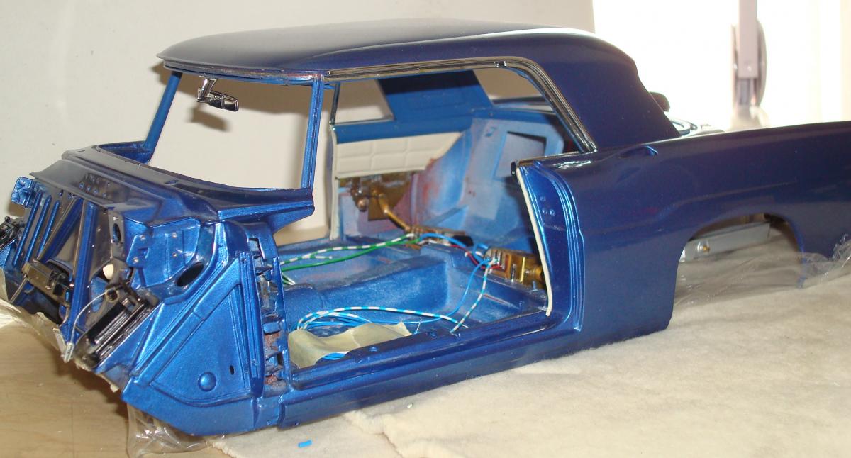
Well, Randy, I would shame me if I did all that work and quit when some difficulties are coming...And it's not yet over: As everything was once installed and functioned correctly, I assumed that the RH door would be easy, but it was not. It was like the parts were done for another model…The frame for the vent window was too tall; it was touching the gutter at the roof. Why? I don’t really know as the holes to attach it at the door were the same as previously. Even by scrapping the paint under the gutter was no help, I had to elongate the holes to lower that assembly until it was just no more touching the gutter. Then, the side window was touching the quarter window, no matter how I tried to adjust it. Finally, I had to shorten the window’s frame by almost ½ mm. Once those corrections were done, I noticed that the motor at the window needed more power, therefore the 3 V for the quarter windows are welcome for the front too. Of course, with that tension, the windows are really fast; I prefer that situation as being forced to help them with the fingers… I assembled the window module to the door with all the needed screws and connected the wires from the arm rest/switch to the ones from the door to test if all was right. The side window still got up and down but the vent window refused to move! The motor was turning, but the clutch was slipping. Once again, everything went out; I did a small rework at the clutch and added some viscous material at it. This time, I was more careful and tested the function and installed the door into the body (to check the clearance) at each new step. The attached picture is showing the final testing for the switches and motors. I assume that the LH door will give the same amount of trouble…
-
Roger's handcrafted 1:12 scale models
Roger Zimmermann replied to Roger Zimmermann's topic in Our Cars & Restoration Projects
Logically, once the headliner was installed, I had to install the quarter windows. Sometimes ago, I wrote that I expected difficulties…I’m not disappointed, they are coming! I assume that I never tried the quarter windows with installed roof moldings, what an error…The groove at the roof is not deep enough, not by much: about 0.3 mm (0.01”) would have been enough that the widow is not touching the channel. With 1.5 V, the LH quarter window is stuck in the middle of its travel, either up or down. I tried to modify a bit the roof moldings; I won maybe something, but not enough. What to do? I’m trying with 3 V, which is quadrupling the power. With that boost, no problem the window is going up or down without problem, but much faster! The RH quarter window is functioning with 1.5 V but very slowly. With 3 V, the window is very quick! I tried to add a resistance but then, with what I have at disposal, the power is marginally increased and not sufficient to overcome the friction. By using 3 V, I’m faced now with another problem: the bulbs for the parking and tail lamps are for 1.5 V; I will have to either add a resistance to the lamp circuit or an electronic device to have 1.5 V for the lamps. By using 2 1.5 V bulbs in serie this would be OK, but I don’t want to modify what is already built, otherwise it will never be finished. I added a circuit board at each motor to facilitate the soldering of the various wires. The quarter armrests are not yet installed, I can do it once the body is on the frame because some screws are behind the armrest.

-
Roger's handcrafted 1:12 scale models
Roger Zimmermann replied to Roger Zimmermann's topic in Our Cars & Restoration Projects
Yes, for a serious modeler, this book is a must (but it can be discouraging...). I also have another one from Gerald Wingrove; I don't regret the buy. -
Roger's handcrafted 1:12 scale models
Roger Zimmermann replied to Roger Zimmermann's topic in Our Cars & Restoration Projects
Well, it depends what kind of details you intend to make. The most logical start is to made a frame. Maybe you want to do one, or maybe just a simplified base for the body and engine. What is the intended scale and what for material you will use? I don't know if this will be your first scratch built model; if yes, don't go too deeply in the details, you will never finished...If I can be of assistance, let me know! Did you assemble and paint yourself the pictured model? Anyway, it's looking good! -
Roger's handcrafted 1:12 scale models
Roger Zimmermann replied to Roger Zimmermann's topic in Our Cars & Restoration Projects
With the addition of the back window inner moldings, the trim for the roof is done. Contrary to the first idea, the rear window moldings are glued to the roof and not attached with screws; I had to modify them to be able to install them. I just hope that the sail panels are not too low; if yes, I will have to rework the inner upper quarter molding as I cannot remove the sail panels. I’m attaching some pictures to show the roof’s trim; you will also notice that the molding on the side of the roof are installed.


-
I have both types. Years ago, there was indeed only the octogonal one available but now I have from both types.
-
It's also my opinion. The other one is for doors and ignition.
-
Roger's handcrafted 1:12 scale models
Roger Zimmermann replied to Roger Zimmermann's topic in Our Cars & Restoration Projects
Do you mean the headlamp "glass" or the bulb? The headlamp was described in the posts 606/607. The bulb is from a store, diameter 3 mm (0.12"). My headlamps are not the sealed beam type! -
Roger's handcrafted 1:12 scale models
Roger Zimmermann replied to Roger Zimmermann's topic in Our Cars & Restoration Projects
Yesterday, I attached permanently the headliner to the body, this is the first trim part installed. I saw that my sequence to assemble the side/front inner moldings and sail panels is not the way it should: I must first install the sail panels and then the side moldings. Makes the whole assembly more difficult. In between, I put the bulbs into the tail lamp assemblies; as I expected, the LH tail light gave me trouble because all the tries I did were without the paint and without wiring, what a difference! The small spring to keep the tail lamp open or closed is way too weak; I’m not doing a stronger one, because the space is so tight. Anyway, the LH lamp is almost perfectly closed… with some persuasion. As you can see from some pictures, the electrical wires for the lamps are now in the way until the circuit can be completed. The headlamps were installed too, as well as some accessories on the RH front wheelhouse. The underbody coating is done too; it’s a mix between some underbody coating from Dupli-Color and black paint sprayed with low pressure to get some texture. The whole is not perfect, it will be hardly seen with all the hardware from the frame and exhaust.


-
Whoa! Nice gun and nice hanger system! You are right, when parts are ready to paint it's difficult to hang them safely. I had my system when I restored my cars, it was much crude as yours!
-
Roger's handcrafted 1:12 scale models
Roger Zimmermann replied to Roger Zimmermann's topic in Our Cars & Restoration Projects
It depends about the size of your screen! On my PC, the doors are larger than on the screen. The wires are oversize: the smaller have a diameter of 0.5 mm which is 6 mm at 1:1 (about 1/4"). In reality, wires used in doors are smaller in diameter. I used mostly milling tools to carve the letters and a file to cut the corners of the "C" and "O", but you are right, no CNC machine. The letters are 1 mm in height or 0.04". Thanks for the comments! -
Roger's handcrafted 1:12 scale models
Roger Zimmermann replied to Roger Zimmermann's topic in Our Cars & Restoration Projects
The doors are equipped with a link to hold the door open; these parts are done since a very long time. I noticed this morning that they must be installed BEFORE the vent window frame. Therefore, I will have to remove the frame from the RH door… I checked also how bad the wiring from the LH door will twist by opening/closing the door. For that, I had to install one more time the LH door. I’m glad that I just have to insert 2 pins and not unscrew/screw the 8 bolts attaching the hinges to the body! Once installed, surprise, surprise! The 11 wires are twisting on their own axis without effort or binding; a good point for the Ford engineering. I like those surprises! -
Roger's handcrafted 1:12 scale models
Roger Zimmermann replied to Roger Zimmermann's topic in Our Cars & Restoration Projects
As I wrote: I could be wrong! -
Roger's handcrafted 1:12 scale models
Roger Zimmermann replied to Roger Zimmermann's topic in Our Cars & Restoration Projects
To make a model or restore a real car are totally different tasks. I restored 3 Cadillacs; I could not fabricate the bad or missing parts with some minor exceptions. Like you, I had to buy them! -
Roger's handcrafted 1:12 scale models
Roger Zimmermann replied to Roger Zimmermann's topic in Our Cars & Restoration Projects
Somewhere in this thread there was the description how the ball joints are done. It must be at the beginning because the pictures are dated November 2011, a long time ago! For the brake line fittings...well turning some brass on the lathe with the appropriate dimensions. the challenge was to find something suitable to reproduce the brake hoses. I fund some rubber string with 1 mm diameter. The fitting is bored with a 1.2 mm bit; the rubber string can be inserted and stay that way without glue. By adding glue the insertion into the bore is sometimes difficult, but it can be done and this way the rubber string stay in place even if you are looking intensively at it! -
On the Jetaway transmissions (from 1956 on Cadillacs, I don't know exactly for Pontiac and Oldsmobile), the sole band cannot be adjusted.
-
Roger's handcrafted 1:12 scale models
Roger Zimmermann replied to Roger Zimmermann's topic in Our Cars & Restoration Projects
For most people, by just adding pictures would be enough. The minority like to know how and why, plus see the result, of course! This is what I think; I could be wrong and not for the first time. -
Ah! only at the rear? As you said, those vehicles can be loaded and surely your wife will not load concrete or sand into that nice car! The radial tires have no influence as the extra width is the same on both sides of the rim.
-
Roger's handcrafted 1:12 scale models
Roger Zimmermann replied to Roger Zimmermann's topic in Our Cars & Restoration Projects
In fact, even wit my tools, this could be done. However, sometimes you have to say Stop! otherwise I could need 20 years for the completion! Am I now in a pure assembly operation? Not at all! There is always something to adjust, modify or fabricate. By assembling the vent window frame, I noticed an ungainly space between the molding and vent window; on a real car the weatherstrip would close the gap. As a weatherstip for the vent window is absurd at that scale, I did a brass part, covered with black type to make the deal. Then I inserted the 5 wires into the RH door’s conduit. I had the choice of color coded wires and red ones. Unfortunately, the color coded wires have a diameter of 0.8 mm while the red wires have a 0.5 mm diameter. I could insert 2 coded wires and 3 red ones. The other door is requiring 11 wires, but the aperture was done a bit larger on purpose. Would I succeed to enter so many wires? If I remember well, I could before, but the conduit was not yet soldered to the door. Anyway, I tried and I managed to even insert one color coded wire, but not two! Of course, to recognize the wires, I will have to paint them at both ends, but on a short distance. I did not that before, because paint is taking space and would probably be wiped away during the insertion.