Roger Zimmermann
-
Posts
3,130 -
Joined
-
Last visited
-
Days Won
24
Content Type
Forums
Gallery
Events
Everything posted by Roger Zimmermann
-

Roger's handcrafted 1:12 scale models
Roger Zimmermann replied to Roger Zimmermann's topic in Our Cars & Restoration Projects
Thanks for the link; unfortunately it's too late! From a French forum I got also other links to products I was not aware. One learn something new each day! -
Roger's handcrafted 1:12 scale models
Roger Zimmermann replied to Roger Zimmermann's topic in Our Cars & Restoration Projects
Thanks for the comments! To pontiac1953: you are not the sole person with that question. Some time ago, I took the decision that I will not do again a complete model, as it "eat" all my time. The next task (don't remember if I mention it already here: the electrical system on the Toronado model is not finished, it will be done. The electrical seat is no more functioning because the track system was not clever: it jams. I will do something similar to the Mark II as the seat in this model is working perfectly. All those improvements will be related here as I don't feel a new topic will make sense. Of course, my reports will not be so often as they used to be. After that, collecting postmarks? One part less lying around: the reveal or belt molding around the rear quarter. I don’t remember if its contour was following exactly the shape of the body; of course, after the paint process it was not. With a slight “massage”, the result was acceptable and I glued definitively with clear silicone. There are most probably stronger products for the task; the advantage here is the ease of cleaning of the excess material once it’s cured. Cyanoacrylate glue is fine but it’s etching the paint. If there is excess glue, the damages are irreversible. At the same time, I’m preparing the windshield for the installation. One element after another!
-
In the February 2019 issue from Collectible Automobile, there is an article over 1945-49 MG TC. Not exactly your model, but the vehicles are very similar.
-
Roger's handcrafted 1:12 scale models
Roger Zimmermann replied to Roger Zimmermann's topic in Our Cars & Restoration Projects
With most of the parts installed, what is still to do? Obviously, the windshield and back window must now be installed. Even with the best I could do, the windows are not a perfect fit; they must be glued to the body to have a decent fitting. The most appropriate method is with clear silicone. In case it oozes on the window, it can be removed when cured. I just have to be careful as too much silicone inside will be extremely difficult to remove. With such kind of cars, there are chromed parts associated with the windows. Before the installation, I checked the fit of the back widow molding and the one at the belt. The dip rail molding was too low; it prevented to belt molding to follow the roof’s shape. A small file shortened the drip molding on both side to allow the belt molding to go under. On the picture, the upper back window molding is temporary installed to help the fitting of the “glass”. It will be glued later. The tape will be there for 24 hours, the time for the silicone to cure.
-
Roger's handcrafted 1:12 scale models
Roger Zimmermann replied to Roger Zimmermann's topic in Our Cars & Restoration Projects
Thanks Pat and John! I too hope to have health and happiness for a long, long time! -
1961 Mercury Meteor 800 restore
Roger Zimmermann replied to Laughing Coyote's topic in Our Cars & Restoration Projects
With a non-metallic paint you can do the body bit by bit. I just hope that you have enough paint for the whole body because, if you need more, you may have a small tone difference! -
Roger's handcrafted 1:12 scale models
Roger Zimmermann replied to Roger Zimmermann's topic in Our Cars & Restoration Projects
Thanks! I'm on my way up! -
Roger's handcrafted 1:12 scale models
Roger Zimmermann replied to Roger Zimmermann's topic in Our Cars & Restoration Projects
A nasty cold let me down for 10 days; fortunately, as I’m almost finished with the model, I did not care too much. When I got better, I could begin the last few hoses for the A/C. 2 are done, one still has to go. To install the one going from the compressor to the condenser, I had to remove the panel holding the hood lock. The first picture from this serie is showing the condenser before panel and grille will hide it. I imagined that the installation of this panel and grille would go in 5 minutes. Oh naïve I’m! Something was jamming: the “horns” from the lower grille molding were preventing the grill to go high enough. When the grille and panel were attached with a few bolts, the assembly pushed the front clip on one side, the hood was not closing properly…I had to remove the lower molding from the grille and see what happens: all good! When presenting the molding to the installed grille, I saw that some holes were no more aligned. I suppose that the several coats of paint are thick enough to upset the original fitting. To elongate the holes was not a big deal, that place is unseen. Once the grille and upper panel were definitively assembled with 10 bolts, I could attach the modified molding with 10 more screws. This time, the support I did long ago was very helpful: the model is not moving during the assembly and the paint well protected. With the car upside-down, it was the opportunity to install the front bumper. Fortunately, I prepared long before a tool to tighten the nuts; it was also used for the rear bumper. A last task had to be done before the car is back on its wheels: connect the parking lamps with the headlamps. As the frame and bumper supports had a good coat of paint, I was not sure it the circuit for the parking lamps would be closed; fortunately, it was! OK, the illumination is rather weak; it’s just for the show. The last picture is showing how the model is getting the current: through the filler tube…Not very spectacular, but again, it’s just for the show.


-
Thanks for the explanation! In that mechanical school, we had such a machine, but not so old...If I remember well, it was not used frequently.
-
1961 Mercury Meteor 800 restore
Roger Zimmermann replied to Laughing Coyote's topic in Our Cars & Restoration Projects
Dear Keiser, if you have some for a 59/60 Eldorado or sixty special, it's maybe time to sold them. I don't know if you saw recently the price they can fetch; it's impressive! -
Even if I did my apprenticeship in a mechanical school (a very long time ago), I don't understand what this monster is good for. Could somebody educate me? One is sure: I would not need this machine for my scale models!
-
Roger's handcrafted 1:12 scale models
Roger Zimmermann replied to Roger Zimmermann's topic in Our Cars & Restoration Projects
Well, Nelson, my words were probably not reflecting my thinking: I know what is under this or that, but I have to study and look at older pictures how exactly this or that element is installed. One point I have often trouble: which screws are used? 0.5 or 0.6mm? Or maybe 0.7? If I was wise enough to write it down at my sketches, it's easy. Unfortunately, I too often forget that small detail (or I did a change during the construction). Something I had problems too: which is the correct assembly order? For example: I wanted to install the A/C condenser on the radiator cradle before the air deflector because I could insert the A/C lines with ease. Not good: there are 3 screws which must be installed before the condenser can be installed. And so on... Anyway, thanks for the kind words! -
Roger's handcrafted 1:12 scale models
Roger Zimmermann replied to Roger Zimmermann's topic in Our Cars & Restoration Projects
That's the problem with a "modern" vehicle, compared to one till the thirties where most mechanical aspects/features were not covered by the body. Indeed, here, with just the body and seats inside, it would do the same effect with much less hours (or years) spent. As somebody once wrote, nobody will know each detail except the one who build it. Most scale model builders do cars from the twenties or thirties, probably because the work can be seen. -
Roger's handcrafted 1:12 scale models
Roger Zimmermann replied to Roger Zimmermann's topic in Our Cars & Restoration Projects
Without the front clip, the model is looking far away from completion. To change this look dramatically, I just had to add the hood and both front fenders. To add some stability, the lower air deflector was installed. I did know that it was a tight fit around the radiator cradle and frame; this time I had to use some persuasion to get it in place. Later I understood why: on the sides, it must go under the fender construction; I managed to put it on top of that lip! I saw that when I wanted to install the screws at the flange: they were not at all aligned. Fortunately, with some more persuasion, the air deflector came out. Once correctly guided, it went in place without problem; I just had to repair the black paint which was damaged during the wrong installation process. The exhaust tubes are also installed; could I now install the grille and front bumper? No, I must first do the missing hoses for the air conditioning system. The fresh air tube for the air cleaner was done since a long time; unfortunately, it’s too short! It will not takes weeks or months to do another one; I just don’t understand why I did not it longer than necessary and cut the excess…
-
Roger's handcrafted 1:12 scale models
Roger Zimmermann replied to Roger Zimmermann's topic in Our Cars & Restoration Projects
No, no! I still need them! -
Roger's handcrafted 1:12 scale models
Roger Zimmermann replied to Roger Zimmermann's topic in Our Cars & Restoration Projects
Well...I put the car upside down and shuttled it. Nothing came out, but it's not the first time. Usually there are nuts or screws which disappear! It's like a real car: usually, the owner or mechanics find later strange things! -
Roger's handcrafted 1:12 scale models
Roger Zimmermann replied to Roger Zimmermann's topic in Our Cars & Restoration Projects
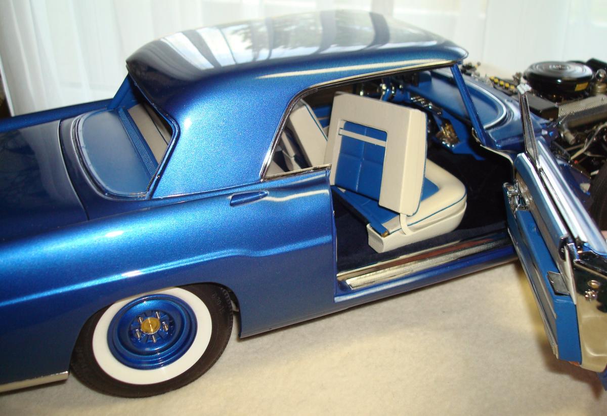
Frankly, I was not very optimistic about the strap links. To maximise the chance of success, I did a cone at the pin to facilitate the insertion, assuming that the hole from the link would more or less align with the ones from the pillar. I also silver soldered a strap at the other end of the pin for the same purpose. After a while, the pin & strap disappeared into the pillar! It will stay here: to rescue it, I should remove the dash, which is out of question. I did a new pin and strap, this time longer as to be able to guide it with the hand. On the RH side, I could see the link when I illuminating the place with a torch. After a while and many tentatives, the pin went into the catch! I cut the excess from the strap and glued the remaining to the body. It was time to go to the other side. Even if I tried to construct the body the same way both sides, I saw nothing at the LH hole. After some hours, suddenly the pin went into the link! Again, some glue secured the strap. The LH is less effective than the RH; anyway, now I can have open doors without holding them. And, as intended, the doors are held at two distinct positions as you can see on the pictures. Now, I can “play” with the front clip.

-
Roger's handcrafted 1:12 scale models
Roger Zimmermann replied to Roger Zimmermann's topic in Our Cars & Restoration Projects
I am what I am, not the best! You are right, the end of the tunnel is near. Yesterday, I had the first try to insert the pin at one of both drag links. It just disappear behind the "A" pillar! -
I'm surprised to see that those cars still had a wood frame for the body.
-
Roger's handcrafted 1:12 scale models
Roger Zimmermann replied to Roger Zimmermann's topic in Our Cars & Restoration Projects
Thanks John! The scale is in the title: 1:12. Technically, it was not a Lincoln; Continental was for some years a separate brand. -
Roger's handcrafted 1:12 scale models
Roger Zimmermann replied to Roger Zimmermann's topic in Our Cars & Restoration Projects
Previously, I told that the curent will be supplied by external batteries through the filler pipe from the tank. This is how I can test the electrical part. As that device is rather crude for the moment, I did not show it. Later, when it will look better than now! -
Roger's handcrafted 1:12 scale models
Roger Zimmermann replied to Roger Zimmermann's topic in Our Cars & Restoration Projects
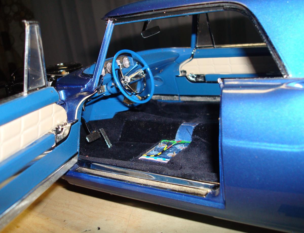
Once the wiring was ready, it was time to hide it under the carpet. I don’t have large hands, but working into the model is not especially easy. I had to shorten the LH kick panel at the bottom. Once in place the question was if I could attach it to the body with the 2 foreseen screws? The slot on those screws is not very deep and the position of the screwdriver is very impractical. First, I searched with a tiny drill bit if the foreseen holes would correspond with the attaching brackets at the body. I did not believe it, but they did! Usually, a couple of seconds is needed to tighten those screws if the setting is right; here I had maybe one hour. For 2 screws! The next step was the seat installation. It was already in the model, I saw no difficulties and it would be done rather quickly. Unfortunately, the reality was very different: I had 3 afternoons to install it! The seat is attached with 4 bolts inserted from under the body. They have to go through the carpet into the nuts from the seat rails. When the seat is into the car, the sight is just zero. So, I prepared 4 studs long enough to go through the carpet and the floor; the studs were screwed into the seat tracks. When one was emerging at the underbody, I secured it with a nut, pushing then on the seat to let the remaining go through the holes. Then, I undid the studs one after the other to use the foreseen bolts. I managed to break one bolt, requiring the removal of the seat to remove the broken bit. After a second similar adventure, I realized that the carpet was the culprit because the attaching points are offset, putting too much stress on the bolts. What to do? The removal of the carpet under the track was out of question; I should have removed the whole carpet but the door scuff plates were glued on the body and the carpet in sandwiched between the scuff plates and body. I did 4 spacers and began again the installation. I just saw that with the spacers the studs were now too short. OK, 4 new longer studs are quickly made. With longer studs the pre-installation of the seat should be easier because I could more or less see the holes on the floor, but it was not! One stud had no envy to go where I wanted, even with some persuasion and chosen words. Finally I was stronger and I could install the bolts. Success! Well, not exactly: the seat was lower on one side. Nevertheless, I tried to install the seat motor. It is attached to the floor with 4 nuts. 2 went well, but 2 could not be screwed in most probably because too much paint was on the thread. The seat had to come out once again. This time, I checked the distance between the attaching points; it was about 1 mm too narrow, maybe the frame was deformed when I tried to insert the studs. I did the correction which was easy as all was soft soldered. At the same time, I cleaned the threads for the motor. New tentative: the studs can now be inserted with ease and the motor is now correctly attached. I had the pleasure to see that the seat was functioning; the seat was at the same “altitude” on both sides, but it was crooked! The seat came out again, but the motor stayed in place. I corrected the tracks to have them square and installed the seat again. Once the connecting rod from the motor was definitively attached to the seat, I could close that chapter! Finally, I put the decal representing the patent plate (Fomoco designation). Practically, the main body is ready with the exception of the windshield and back window, plus the associated chromed parts. The next step will be the inserting of the door strap links, if I can do that. It will be similar to catch a fly with closed eyes: the hole for the shaft is barely visible; see the arrow at the last picture. Maybe I will have to plan a long installation time!


-
1950 Crosley Farm O Road Restoration and more
Roger Zimmermann replied to dalef62's topic in Our Cars & Restoration Projects
The sole method I know is with a torch heating a point and hammering. I'm not good at that, I don't master that technique! In your case, there is maybe another method. Let see what others are telling. -
Roger's handcrafted 1:12 scale models
Roger Zimmermann replied to Roger Zimmermann's topic in Our Cars & Restoration Projects
If the wires soldering went rather well, the result was not what I expected: during the function test, I noticed that when lowering the RH door window from the master switch, the RH quarter window went up! What was wrong? Wiring problem, a short somewhere? When I noticed that by pulling the switch without much force, the quarter window was not moving. Conclusion: something was not quite good in the master switch. I don’t like to open again doors, but I had no choice. Fortunately, my construction is rather service friendly, the switch can be separated without too much hassle. I just had to unbend a contact, bend a bit more another one and voilà, all windows are going up and down as intended!
-
Roger's handcrafted 1:12 scale models
Roger Zimmermann replied to Roger Zimmermann's topic in Our Cars & Restoration Projects
Sometimes things are going well, eh, almost. I had fears to install the steering column because the screws attaching it to the dash are pointing towards the floor and the heads are almost invisible. By putting the model on its side, the situation was not so bad. Once the steering shaft was inserted into the steering box, the assembly was rather stable and I could install the supporting bracket without too many difficulties and without damaging the paint. All is good? Well, not exactly: when the wheels were positioned for a straight drive, the steering wheel was wrong by 180°. At first, I wanted to let it that way, but I did not like that idea. To remove the column was out of question; I tried to remove the steering wheel inside. Finally, I could turn it a half turn and now it’s the way it should. The movement from the wheel to the steering shaft is done with a tiny steel screw. Obviously, this screw will break if too much effort is required. As it’s not a toy and will be seldom “used”, I can live with that. And now? Another fear: soldering the wires from the LH door to the board seen on the picture…Anyway, the number of parts lying in the display cabinet is slowly diminishing!