


Roger Zimmermann
-
Posts
3,130 -
Joined
-
Last visited
-
Days Won
24
Content Type
Forums
Gallery
Events
Everything posted by Roger Zimmermann
-

Scale model 1932 Cadillac V-16
Roger Zimmermann replied to Roger Zimmermann's topic in Cadillac & LaSalle
Perfect Alex! I do appreciate a lot. Anyway, it's all the time better to do pictures on a clean/painted part, but I had not the choice! -
Scale model 1932 Cadillac V-16
Roger Zimmermann replied to Roger Zimmermann's topic in Cadillac & LaSalle
Alex, may I ask you a favor? As I wrote the other day, I did many pictures from that restored frame. There was one wheel, still to be cleaned and painted; I did also pictures from it but I missed the relation between the front and the rear spokes on the hub. If you look at the attached picture, there is a good view from the front spokes, but unfortunately, the rear ones are in the dark! What I would like to have is a similar picture, taken perpendicular to the wheel from about the same angle but where both rows are visible at the attachment point on the hub. For that, the camera must be a tad lower in direction to the center of the wheel. Thanks in advance!
-
I found my luck (maybe)!
Roger Zimmermann replied to Roger Zimmermann's topic in Our Cars & Restoration Projects
Thanks Chris! Today, I drove Popeye for the fist time. During that 3/4 of an hour, I was really happy: the suspension is acting the way I like, soft, almost like a ship on calm water! There will be somme little things to improve (the car is 47 years old, I always have to remember that it's not a new car), like a better cleaning of the inside trim/chromed parts. Overall, I'm really satisfied! -
Roger's handcrafted 1:12 scale models
Roger Zimmermann replied to Roger Zimmermann's topic in Our Cars & Restoration Projects
In fact, the shop manual is providing a good sectional view of the engine. I did measure key dimensions. Some were not possible like total height, the sectional drawing will help. The most measurement effort was done at the chassis because the side view in the shop manual is so small to have details. And boy, those frames are complex with many cast supports for the springs; they will be a joy to replicate! We stayed 1 1/2 days at the shop hosting the frame. At the end, there would still be a lot of measurements to do, but after a while, you don't see anymore what's important or not. -
Scale model 1932 Cadillac V-16
Roger Zimmermann replied to Roger Zimmermann's topic in Cadillac & LaSalle
Yes, Alex. I was not aware about this complexity. It will be probably the most important expense for the model, but I don't regret it; it was the sole opportunity to see the engine and frame alone. -
Here are some pictures from the carb I saw last week. I did not more pictures from the carbs as they are rather well described in the shop manual. According to the one who restored the frame, those carbs are reproduced in bronze. And accordingly expensive!


-
Scale model 1932 Cadillac V-16
Roger Zimmermann replied to Roger Zimmermann's topic in Cadillac & LaSalle
At the end of last week, I drove 600 miles one way to measure and take pictures from a restored frame and engine. During 1 and half day, I was over and under that frame to measure all what I could. I was amazed how complex those cars were build during that time. Just the hand brake has an impressive number of parts when 20 years later a cable or two did the job. Same for the mechanical service brakes; to me, it's a wonder that all those bits were usable! There were still missing parts on that assembly: no air cleaners, the radiator is still to be overhauled and was not installed. Therefore, I may ask once for some dimensions, but for the next few months (years?), I'm set. The story about this construction will be related in my tread located in "our cars and restoration projects", continuing the Continental Mark II story (and the other ones too!). -
Roger's handcrafted 1:12 scale models
Roger Zimmermann replied to Roger Zimmermann's topic in Our Cars & Restoration Projects
While people are waiting to see the continuation of the Avanti, I already moved to another project: I will do a 1:12 1932 Cadillac V-16 engine and frame. Last week, Christine and me drove about 600 miles one way to measure and take pictures from a restored engine and frame. It was the last moment to do that: this week, the body will be mated to the frame. We came back Sunday, tired, but I'm happy to have enough info to begin soon this new project. Therefore, when the Avanti story will be over, a new one will come! -
Roger's handcrafted 1:12 scale models
Roger Zimmermann replied to Roger Zimmermann's topic in Our Cars & Restoration Projects
Feb. 4, 2008 I could not take the small problem with my windows out of my mind: when the window was up, the string had a good tension. When the window was down, I could turn the handle 1/2 turn before something was happening. Therefore, I decided to build a tensioner. It's working well, the risk that the string is getting away from the guides is gone. The window's guide on the left does not belong to the module, the correct guide is part o the went window's frame, attached to the door. However, to verify the function, I had to add one; it will be removed when all is OK. The back of the module is not esthetically very pleasant; it's about the same in real cars: the owner does not see it!
-
Roger's handcrafted 1:12 scale models
Roger Zimmermann replied to Roger Zimmermann's topic in Our Cars & Restoration Projects
Feb. 03, 2008 When I was rebuilding the model, I put the same question about how to attach the handles to the doors to a French forum. I got more answers than here, just because it was actual. Most answers were impractical because too complex or not taking in account the dimensions. Generally, on a model, when something is moving the difficulties are sometimes unsuspected from the viewers. For example, as in most scale models, the windows are in the open position. To replicate that, a simple molding representing the top of the window frame can be attached at the door and it's done. When the windows are operational, it's more complex: the windows must have enough space into the door, guides must be designed to avoid jam, the windows must go completely down and not stop mid-way because attachment parts are too large and the system to let the windows go up and down must be rather reliable. At that day, the windows are going up and down, but not yet the way I want. The first two pictures is a view from inside, window up and window down; the last one is showing the module's back; very simple. I still want to make holes for easy verification (and not to do the model less heavy!).


-
I found my luck (maybe)!
Roger Zimmermann replied to Roger Zimmermann's topic in Our Cars & Restoration Projects
Thanks Keith! The speed limit is 120 km/h (75 MPH) on freeways; usually 80 km/h (50 MPH) on "normal" roads and 50 in town (31MPH); there are of course sometimes lower speed limits. I was lucky: by law, the tires speed rating should be equal or higher than the vehicle max. speed; the tires I have are rated for 180 km/h (112.5). I corrected my previous post to be clearer! -
Roger's handcrafted 1:12 scale models
Roger Zimmermann replied to Roger Zimmermann's topic in Our Cars & Restoration Projects
January 31, 2008 Well, nobody scratched his head to try a solution. It was to be expected as indeed this forum is for real cars, not scale models! The picture is showing the solution: shafts from both handles have been milled to form a square. The square shaft will be pushed into the drum or, to open the door, into the swinging lever. There is some interference to keep the levers where they belong but not too much to be able to take them out just in case. The rear guide for the window is assembled to that module as you can see.
-
I found my luck (maybe)!
Roger Zimmermann replied to Roger Zimmermann's topic in Our Cars & Restoration Projects
By the way: the max speed from this car is 207 km/h or 129.4 MPH. Would you drive this small elephant at this speed? -
I found my luck (maybe)!
Roger Zimmermann replied to Roger Zimmermann's topic in Our Cars & Restoration Projects
Since today, the car is totally mine. The guy who prepared it went to the government agency early afternoon; I have the "title" and the car is into my garage! Sorry, I did no picture I was catch by surprise!
-
Thanks for the explanation! Of course, the flywheels must have an axle to be able to turn, it was what I did not see. Sometimes my brain is limited!
-
I admit that I don't understand how this engine was built. You had a lot of work and trouble to attach something with these 6 screws and turn the flywheels. What is the purpose of all that? Now you will insert the crankpin held with 2 nuts...I looked back 2 or 3 pages but I did not find the explanation of all that trouble, if there is an explanation. Mike, can you bring some light is that complicated system? Thanks!
-
Roger's handcrafted 1:12 scale models
Roger Zimmermann replied to Roger Zimmermann's topic in Our Cars & Restoration Projects
January 30, 2008 The second vent window assembly was much quicker done than the first one because the "how to do" questions were all answered. Now, it's the turn to the side windows which will go up and down, as on the original model. Here too, I have to study to find a solution which is practical to do and reliable. On the first picture, you see the old door trim panel. They will not be used again, with 2 exceptions: the handles for the window and to open the door from inside. However, those parts will be modified for their new lease of life. Stains from the old cement are clearly apparent; this one of the reasons why I wanted to refresh the model. Next picture: the other side of the scenery: the window frame was attached to the string, allowing the movement. I was probably a pioneer at that time: the unit is to be considered as a module: all the parts and the leather were assembled outside of the model and, with some contorsions, the assembly was attached to the door with glue. This is now my dilemma: I don't want that the trim panel be assembled like I did more than 40 years ago (with glue). I will continue the module idea, just partly: the window and door aperture mechanisms will be assembled outside the model. The completed module will be installed on the doors with screws; the trim will be installed separately. Now, there is a problem which must find a solution: when the trim panel is lastly installed, how can I insert the handles securely and, if necessary be able to remove them in case something is getting wrong into the door? After a good brain storming, I found a solution. On the last picture, the handle to open the door is temporarily installed. But how? Will somebody in 2019 guess what I did 11 years ago?


-
Roger's handcrafted 1:12 scale models
Roger Zimmermann replied to Roger Zimmermann's topic in Our Cars & Restoration Projects
January 11, 2008 If the windshield, quarter windows and rear window are done, if I'm right, the windows at the doors must be done. The begin is with the went window because it must be adapted to the slope of the windshield and its frame is the guide for the door's window. A vent window is not quite exiting; however, it's more complicated than anticipated. The various parts are shown on the first picture. On the left, the guide for the window; next to it the frame for the vent window with its locking lever to keep the vent window closed when required. Further on the right, a filler with a double function: it attach the unit to the door and, when painted black, it will represent the rubber seal. The last part which is indeed a cap will be chromed and will give the illusion that this chromed part is maintaining the assembly to the door. The next picture is showing how the assembly is attached to the door. The next view when the door is closed: the vent window is closed too. The tape is to maintain the windshield molding in the correct position during the construction of the vent window assembly. You may notice a very long shaft at the top of the vent window. During the definitive assembly, the glass will stop the shaft and the chromed frame will prevent that the shaft is escaping from above. The last picture: the vent window is open. As you can see, the locking lever can be moved; it was a difficult part to design and to do. There is no glass installed, it will be done during the final assembly. Now, I have to do the other side…


-
Roger's handcrafted 1:12 scale models
Roger Zimmermann replied to Roger Zimmermann's topic in Our Cars & Restoration Projects
Dec. 19, 2007 Once the quarter window's frames were done, I had a look at the rear window. It gave me headache since a long time, especially the garnish molding. Good news for me: I can save the window itself which was done about 40 years ago; only some small corrections at the edge. The bad news: the chromed molding is not quite following the aperture and the chromed did suffer from attempts to correct the shape. With a bit of brass 2.5 x 2.5mm, I did a new molding with some wasted brass: the finished molding is 1.7 mm wide and .6mm thick. The assembly is just resting into the aperture; it will better looking when glued. The small hammer in the foreground is a fantastic tool: with it, I can bend what must be bent or I can do delicate adjustments!
-
Roger's handcrafted 1:12 scale models
Roger Zimmermann replied to Roger Zimmermann's topic in Our Cars & Restoration Projects
Dec. 11, 2007 As I have less external work those days, I could progress with the side windows as you can see. As on the real car, the quarter windows can be opened for ventilation. The whole unit is assembled like a module, to be inserted into the body. On the pictures, a temporarily window is used to maintain the parts together; the vertical part will not be soldered to the "J" frame because I could no more insert the "glass". The locking lever is not yet done. The parts are not yet perfect; some work is still needed before the polishing for plating. The reddish dust is not rust but brass dust. On the model, the windows will stay closed.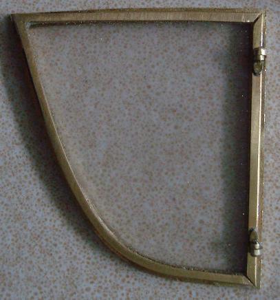


-
Roger's handcrafted 1:12 scale models
Roger Zimmermann replied to Roger Zimmermann's topic in Our Cars & Restoration Projects
Dec. 07, 2007 After doing the windshield and its garnish molding which will be chromed, I'm beginning the frames for the side windows. First, the quarter windows. On that picture, the molding under the roof and the one for the center pillar are temporarily installed. The second picture is showing the parts for those quarter windows. The still unassembled thin parts are indeed shaped as a "U" for the plastic window. Missing for the moment are the hinges and the locking lever.

-
Roger's handcrafted 1:12 scale models
Roger Zimmermann replied to Roger Zimmermann's topic in Our Cars & Restoration Projects
Oct. 10, 2007 Long before I began that reconstruction, I did name plates for the Toronado and, recently the Studebaker name plate for the Avanti. Sorry for the dust/dirt; I usually forget the cleaning before taking a picture. The letters "OLDSMOBILE" are OK in my opinion; the name plate Studebaker too, but the plates "Toronado" (11mm in length or 0.43") could be more precise; I will survive.
-
I found my luck (maybe)!
Roger Zimmermann replied to Roger Zimmermann's topic in Our Cars & Restoration Projects
The car still must go to the government agency to get licensed. As today is a national holiday, I hope this will happens next week. Anyway, it takes longer than expected! -
Scale model 1932 Cadillac V-16
Roger Zimmermann replied to Roger Zimmermann's topic in Cadillac & LaSalle
I just have one black car, I know your pain! -
Scale model 1932 Cadillac V-16
Roger Zimmermann replied to Roger Zimmermann's topic in Cadillac & LaSalle
Thanks for the pictures; I suppose most of the work is behind you. Upholstery; if still to be done, is not so complex, just expensive! The wheels are red; will they stay like that? Do you already know which color the car will be? Right now, I have several little things which are slowly "cooking". I hope to be in a position to tell in 10-12 days what is in the back burner.


